Philips VAM1202 Transport
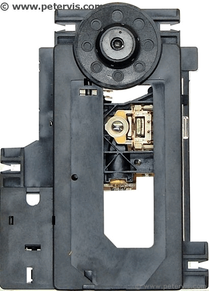
The VAM1202 is a laser transport mechanism manufactured by the Philips Corporation in China. It consists of the laser, spindle motor, sled motor, and the focusing mechanism.
This article is about how to replace this mechanism. The example CD player is a Marantz CD6000 OSE, however, this laser mechanism was used in many other players, and the steps will be similar if not the same.
As usual, never attempt any kind of repairs on electronic equipment if you are not qualified to do so. I am an experienced engineer, and this guide is for those that are experienced and qualified.
An old CD player is generally not worth repairing; however, if you have a high-end CD player such as a Marantz or a NAD, then perhaps it might be worth paying a few bucks if it is going to be a cheap and quick fix. Of course, there are no guarantees how long the new one will last, but if you can get more than one year of use out of it then I suppose it is worth a punt.
I bought the replacement VAM1202 on eBay and it arrived from China. I paid around £8.00 for it, which was the cheapest deal I could find. I was not going to pay any more for my old Marantz. It is an old player, cannot play MP3, struggles will CD-R, why waste money? New CD players are dime a dozen these days, and they play MP3, WMA, and a whole bunch of other formats. However, I figured this was a high-end machine; it has a nice metal case, so it was worth a go.
Replacing the unit was quite easy, it requires just a bit of soldering skills, and assembling. The new unit does not come with the wires attached, and therefore one has to remove the wires from the old unit and solder them to the new one. This is not a big deal as there are only six wires in total to solder. Two for the spindle motor, two for the switch, and two for the sled motor. If I had some trainees at Vis Labs, then I would probably give it to them.
My mechanism came packed in some bubble wrap, in a small envelope. There was no installation manual or any instructions. There is some documentation available on the Internet for this laser mechanism. However, it is not required if you are able to solder the wires exactly as the old unit, and fit it back exactly as it used to go.
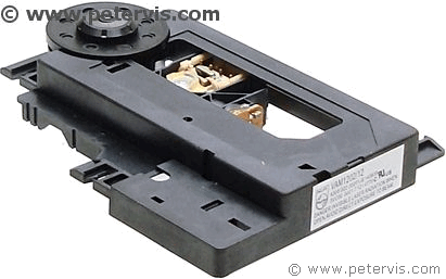
There is a label on it with the Philips logo. It seems to be genuine from their factory in China.
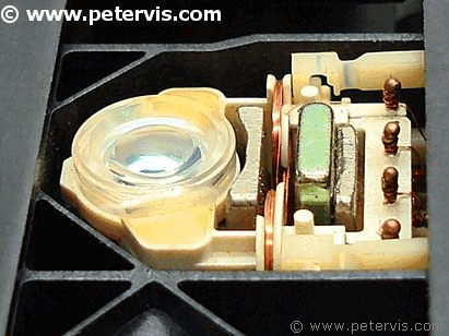
The focusing platform seems to be identical to the old one. You can see photographs of the old one in the Marantz CD6000 OSE article on this site.
The lens on this new unit is clear. On my old one, there was a dark spot in the middle, kind of like a cataract. However, on my old unit, the laser had burnt out from excessive use.
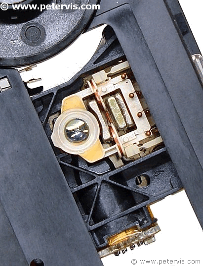
There seems to be a slight improvement in the lens.
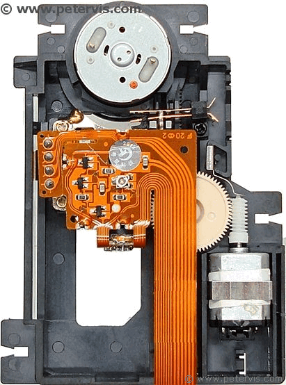
The spindle motor and sled motor appear to be the same type.
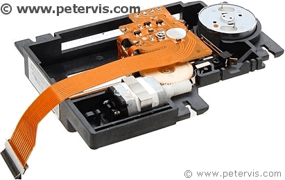
Apart from slight differences, it is identical to the original one.
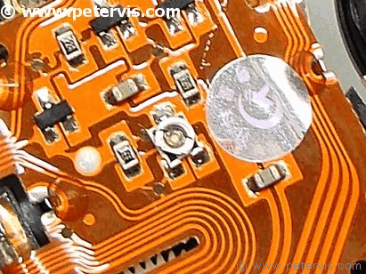
Of course, you should never fiddle with this preset as the laser calibration is set at the factory. However, if you were messing with it, then this image might help as it shows how mine was set when it arrived.
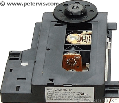
The label reads VAM1202/12.
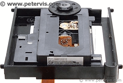
The first task is to fit it back into the platform. It attaches to four rubber suspension pillars.
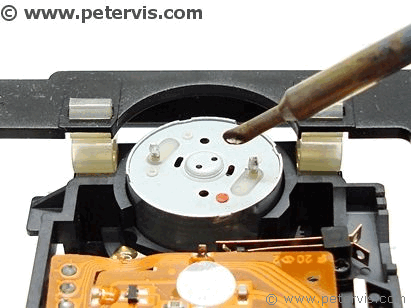
You need to keep the heat to a minimum, and make some nice solder joins. I am using some nice environmentally friendly Omega solder, which is 100% tin and free of lead, rosin, and halides.
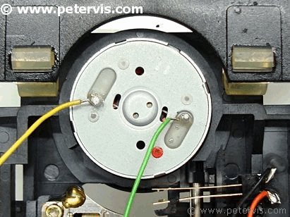
The spindle motor has one terminal with a red spot next to it. The green wire solders to that terminal.
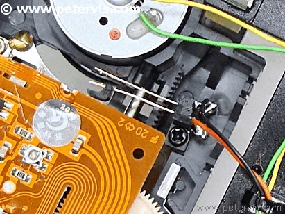
The orange and black wires are for the switch. The switch wires can connect either way.
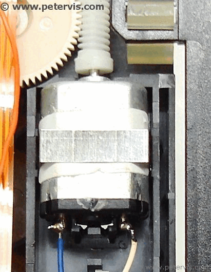
The blue and white wires are for the sled motor. The blue wire connects to the Left terminal as shown in the photograph. I installed mine exactly the same way as the original.
If you connect them the wrong way round, then the sled will remain at the outermost edge of the CD, instead of the innermost.
The service documentation indicates that the white wire connects to the terminal marked with a red dot. Unfortunately, one the new VAM laser mechanisms, there does not appear to be this marking.
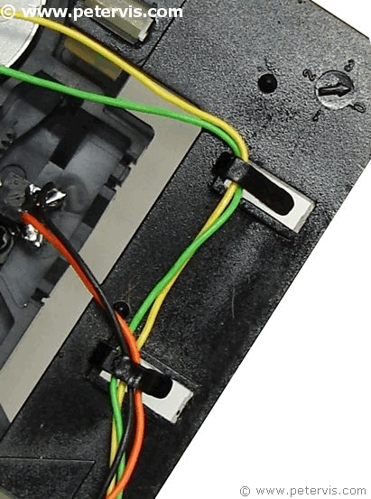
Make sure the clips secure the wires. If they are loose, then they will get into the sled track and prevent it from moving freely.
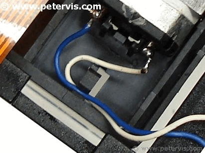
A plastic clip as shown here secures the sled motor wires.
Make sure there is enough free wire for the platform to move and rise. If you have not left enough free wire, then the platform will not rise high enough to engage the motor with the CD.
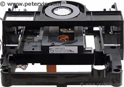
The whole platform then slides into the rest of the transport mechanism. There are special grooves into which the platform rides. You will need to make sure that the platform is riding in these grooves.
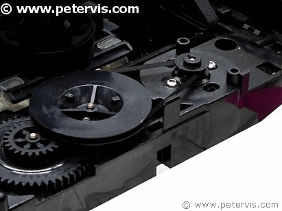
When I assembled mine and tested it, I got TOC reading followed by Error, however, this time the CD was spinning which was a good sign. I could not figure it out at first, then realised that the platform was not raising high enough to engage the CD.
The problem was with the wires not being loose enough to allow the platform to move high enough, and the loading tray drive belt was slipping and needed cleaning. Once I sorted that out, my CD player worked fine! As soon as it started working, I quickly packed it up. It is amazing how much time it all took. I was hoping to do it all in less than five minutes, but it ended up taking over three hours!
If it breaks again, I will not be replacing it. I will probably remove the whole mechanism and main board and install something else like a Raspberry Pi.