LM386 Circuit Build
This page shows how to build the amplifier stage. I hope that you have already built the TA7642 Radio IC stage. This page does not show the components for the radio stage, because the focus is on the amplifier stage.
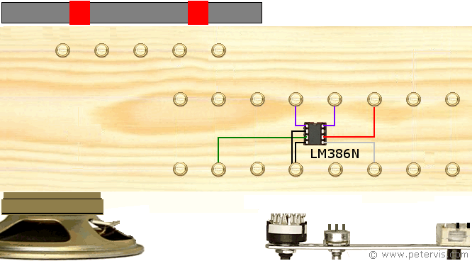
I used a chip socket and soldered small extension leads to them so that they could be connected to the screw cup system. Once I received the IC, I simply had to pop it into the socket.
It is a very simple chip and I have written more information about it in the LM386 Audio Amplifier article. You should bookmark this page for reference, or possibly open it in another tab of your browser. This reference also contains information about the pinout, and the different versions that are available.
The lesser-known facts about this IC are that it comes in three main flavours, each with a different power output rating. You could use any of the versions for this project though.
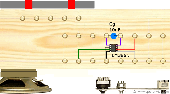
Cg is a 10 µF electrolytic capacitor connected between pin 1 and pin 8 of the chip. Note, that the negative terminal of the capacitor connects to pin 8. This will provide a maximum gain of 200 from the amplifier. This is very useful if your radio is picking up faint radio signals in the DX band.

R2 is a 10R resistor, and C4 is a 0.047 µF capacitor. This small RC network is critical and forms part of the snubber circuit, which also helps to stabilise the output. Without this RC network, you will get feedback oscillations at higher gain; therefore, it is essential that you connect these components.
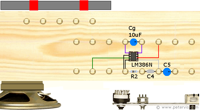
This audio amplifier chip requires an output capacitor.
C5 is 220 µF / 16 V. I managed to find a recycled high-end Elna capacitor so that I would get the best possible sound.

In this step, you have to wire the loudspeaker. I am using a recycled loudspeaker, which has an impedance of 8 Ω. A loudspeaker normally has a positive and negative terminal. The positive terminal connects to the capacitor side as shown by the red line. The negative terminal connects to the ground.
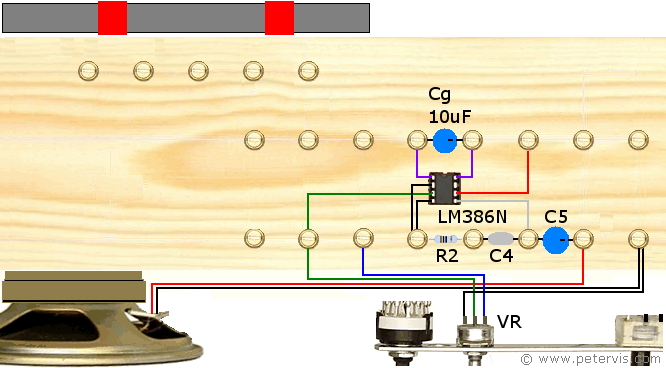
In this step, you wire the 10-kΩ potentiometer VR. The leftmost pin connects to ground, that way, when the slider shaft turns anticlockwise the sound volume reduces. The rightmost pin (blue wire) receives the signal from the TA7642 Radio IC pin 3. The centre pin (green wire) is the slider terminal, which feeds the signal to the amplifier chip.
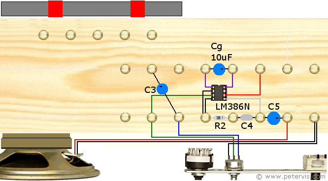
C3 is an electrolytic capacitor of value 1 µF. Its positive terminal connects to the potentiometer terminal.
C3 is an inter-stage decoupling capacitor. The signal from the TA7642 Radio stage is fed to the amplifier stage through this capacitor. The purpose of this capacitor is to allow the audio signals to pass through, but block DC current transferring between the stages.
The value of the electrolytic capacitor is not that critical and you could use any value up to 4.7 µF.
This Article Continues...
TA7642 AM Radio - Project TomTA7642 AM Radio Baseboard Construction
Ferrite Coil
TA7642 Ferrite Coil Connection
Radio Stage
TA7642 AM Radio IC
TA7642 Power Resistor Rp
TA7642 Circuit Build
Amplifier Stage
LM386 Amplifier - TA7642 AM Radio
LM386 Circuit Build
Misc
TA7642 Circuit
TA7642 AM Radio Parts List
TA7642 AM Radio Parting Shots