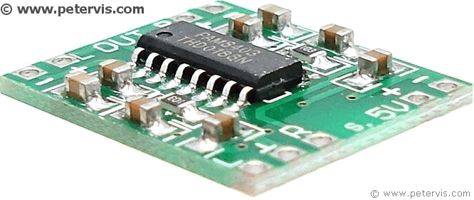
PAM8403 Ultra Miniature Digital Power Amplifier Board Class D 2x3W T5

This is a project audio amplifier circuit board based on the PAM8403 stereo amplifier chip. It is a 3 watt Class-D stereo amplifier capable of operating on a voltage as low as 2.5 V and up to a maximum of 5 V.
Power Analog Microelectronics Inc., part of Diodes Incorporated, manufactures the chip, and they are currently one of the best semiconductor manufacturers.
This chip is capable of driving a conventional loudspeaker directly, without the need for an output capacitor. With a 4 Ω loudspeaker, one can expect a maximum of approximately 3-watts output, when powered by a 5 V source.


Pinout

This chip provides a pulse width modulated output to drive a conventional loudspeaker, hence it has a dedicated pair of pins for each output channel, and there is no common ground.
Pin 1 is the left channel positive output, and pin 3 is the left channel negative output. Pin 16 is right channel positive output, and pin 14 right channel negative output.
The analogue input signal to this board consists of left, right, and common ground. Pin 5 is an active low mute control for the volume. For more information, please consult the PAM8403 datasheet.
Class D Audio Amplifier

A transistor is most efficient when it is either fully conducting (saturated) or fully OFF. Any state of conduction in-between is inefficient and results in power dissipation through heat. Analogue signals by their very nature have in-between states, and using them to drive a power transistor is inefficient because it will create those in-between states of conduction. So what is the solution you might ask? The solution is Pulse Width Modulation (PWM). This is where you are using digital pulses to drive an analogue device such as a loudspeaker! So how does the chip accomplish this?

As you can see in the block diagram, there is an internal oscillator, which generates a very high frequency digital square wave used as the carrier. The incoming analogue audio signal feeds the modulator block, together with the high frequency digital square wave. This stage then modulates the square wave into a PWM signal. A pulse-width modulated signal is typically a square wave, which has had its width adjusted (or modulated) in proportion to the amplitude of the analogue input signal. Although there are variations of this modulation technique, many of which are corporate secrets, it usually employs some form of PWM.
As you can see from the block diagram, the driver stage receives the pulse width modulated signal, and this stage consists of high-speed CMOS power transistors, which drives the loudspeaker. This is a very simple example of Class-D operating principle, and for the most part, it tends to be the same in most amplifiers. If you can remember the basic engineering principle of Class D, that there is always a modulator block, then that goes a long way to understanding these types of designs. It is also worth remembering that there is usually an analogue input signal to the modulator, and an oscillator producing a high-speed square-wave carrier. The carrier then feeds the modulator, and the modulator generates the PCM signal from that.
Review

The cost of silicon chips is always falling and it is amazing that today you can buy a Class-D stereo amplifier for as little as a pound on eBay, including postage! Granted, that the circuit board is 20 mm × 18 mm, approximately the same size as a first-class British postage stamp with SMD components, however, it is still a very good bargain, for a ready assembled board.
The total harmonic distortion plus noise is as little as 0.11 %, which allows this chip to produce very high quality sound. With good speakers, you should get the entire bass and tone that you would not normally be able to hear in a conventional amplifier. It is also worth noting that this amplifier IC is very efficient with ultra-low power consumption, and a rated efficiency of 90 %, hence it does not produce as much heat as conventional amplifiers.
There are very few disadvantages for this class of amplifier output, however, one thing to be aware of is that they usually have an internal oscillator operating at high frequency. In the past, this posed a problem as RFI noise radiated outside of the chip package. However, this particular chip uses more advanced silicon technology and the noise figures are negligible.
