555 PWM Circuit
This 555 Pulse Width Modulation (PWM) circuit uses two 555 timer ICs to generate a signal for use in an industrial control system. The first 555 timer (IC1) is an astable mode, whilst IC2 is in monostable mode; therefore, we have to use the correct formulas when calculating the component values to set the pulse width. In this example, we look at how to calculate the period, and the value of variable resistor (VR) setting required for the duration when the PWM signal is HIGH.
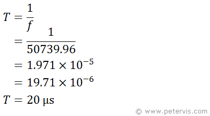
To calculate the "time period" of the astable section, we use the standard astable frequency formula usually given. Although this will give us frequency f, we can then use the famous (T = 1 / f) formula to find the "time period".


If we wanted the PWM output to be high for 1.5 µs, we can calculate the value VR should be using the standard formula given for a monostable. We just have to transpose it for R.

Hence, the scientists should set variable resistor (VR) to 6.20 kΩ

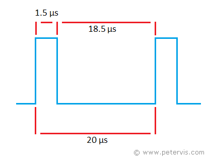
If the period were to be 20 µs, and it was high for 1.5 µs, then it follows that it must be low for 18.5 µs, because (20 µs - 1.5 µs = 18.5 µs).
