Sinclair Micromatic Pocket Radio

The Sinclair Micromatic was a two transistor AM pocket radio manufactured by the Sinclair Corporation. This was the world’s smallest pocket radio designed and marketed by Sir Clive Sinclair, one of the most successful British business entrepreneurs of the 20th century. Amazingly, the radio circuit has only four semiconductor devices consisting of two transistors, and two diodes. The transistors consisted of a pair of ME4102 devices normally used for general-purpose amplifier applications. These were one of the earliest NPN silicon transistors with a maximum rated gain (hFE) of 600, and Ic of 1 mA. Today we would use something like the general-purpose BC549C with a gain (hFE) of 800, and Ic of 2 mA. The AF output of the circuit drives an earpiece.
Reflex Pocket Radio
Reflexing is an old technique stemming from valve electronics. Valves were bulky and expensive and engineers had to find novel ways to increase the signal gain by using them more than once. The RF signal amplifies and demodulates the first time, and then its audio frequency component amplifies the second time round. Using a valve more than once in this way was more economical. Transistors like all new technologies were expensive and therefore engineers employed the same principle of "reflexing".
Circuit Diagram

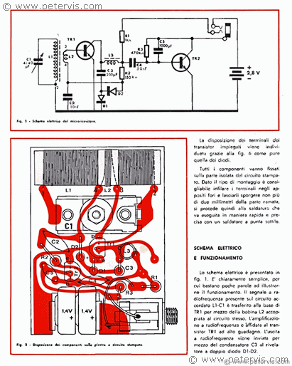
Reflex radios usually have two radio coils. The second coil L2 is usually around ten turns of copper wire and wound over the main coil L1, forming a closely coupled tuned circuit. Both L1 and L2 windings are usually in the same direction. The smaller coil L2 is normally on the earthy side of the main coil L1, however in this design it is slightly off-centre to the earthy side. The impedance of L2 usually matches closely to the base impedance presented by TR1. In this circuit, you will notice that there is no regeneration control, and the internal impedance has fixed the Q multiplier. This very ingenious method also helps to reduce the component count. They must have had a very clever engineer trying out different ways to improve the circuit. Back then, there were no SPICE simulators and engineers had to manually experiment with a circuit to find better ways. L1 is the main ferrite loop aerial with a 40 pF trimmer variable capacitor across it. The collector of TR1 will contain an amplified signal consisting of both RF and AF components. At this point in the circuit, we do not require the RF component to be present and we short this part of the signal to ground through C3 and D1. The RF choke L3 further chokes the RF frequency, preventing it from moving forward to the second stage amplifier circuit consisting of TR2. However, the choke allows the AF to pass through. Once the AF signal emerges at the other end of L3, resistor R2 re-introduces some of the AF signal back into the coil L2, hence TR1 is used the second time round to amplify the AF component.
Obviously, with AF feedback, you will get whistling, howling, and rude noises... :-) Therefore, D2 maintains the feedback to a constant level through its junction voltage. It is a bit like a pressure cooker valve, which comes into play when there is too much pressure. My friend Jon had one of these radios and he remembers that there was an additional positive feedback path between L3 and the ferrite rod. By bending L3 over, it was possible to increase the sensitivity. However this was at the expense of stability.
The second stage amplifier consists of TR2. Its purpose is to amplify the AF component of the signal. R3 provides self-biasing to the base junction of TR2, whilst C5 provides filtering to improve the bass level of the AF signal. It makes a big difference when you are listening through the earpiece. As you can see from the circuit diagram, it is a highly optimised circuit, where each component performs at least two other functions.
Printed Circuit Board

A pair of miniature 1.4 V button cells, which would have lasted a very long time, powered this pocket radio circuit. The tuning capacitor was a simple trimmer with a pair of metal plates. The trimmer screw was fitted with a large plastic control knob at the front of the radio.
Manual


For Sale – eBay
eBay is the most likely place where you will find one of these for sale. I have seen them a few times and there is always a bidding frenzy. I would of course love to photograph one of these for my article but I have not been lucky to date. Just recently, I managed to find a "High Kit" brochure in the skip of a charity shop... Yes, my talents have no bounds; I will even jump into a skip to save something! The manual also had a circuit diagram, and fortunately, it was in the beautiful Italian language, La ringrazio molto!
Related Pages
Crystal RadioSpy Crystal Radio - Budget Cuts
One Transistor Radio
Two Transistor Radio