Differential Signal Transmission
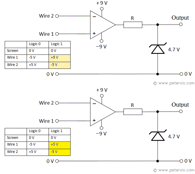
Differential signal transmission is the transmission of same data over two independent conductors, however each conductor uses a complementary electrical protocol. For example, in one wire, +5 V could represent binary 1, and -5 V binary 0. However, in the other wire, +5 V would represent binary 0, and -5 V binary 1. Although at first sight it appears wasteful to have two conductors carry the same signal, there are benefits to sending information in this way. Firstly, the opposing magnetic fields that each wire produces cancel each other out thereby reducing crosstalk. This is extremely useful when using twisted pair wire to send data over long distances. Secondly, since electrical noise would occur in both wires equally, subtracting the two signals would eliminate the noise (suppression of common mode interference and ground noise).
At the receiving end, these types of signals usually feed a comparator (differential operational amplifier) which would subtract the two signals to produce a logical output.
For conventional logic (TTL), we require a positive voltage output from the operational amplifier to represent logic 1. Since wire 1 protocol is +5 V for logic 1, we connect it to the non-inverting input. However, since wire 2 protocol is -5 V for logic 1, we connect it to the inverting input, which inverts it into a positive output. The final output from the op amp will be close to +9 V, which is incompatible with TTL protocols, which require +5 V to represent logic 1. We therefore use a Zener diode and voltage drop resistor R to clamp the voltage to 4.7 V.
