Schmitt Trigger Op Amp
A Schmitt trigger is a circuit that transforms digital signals with slow rise and fall times into sharp vertical edges, by removing jitter and electrical noise from the signal. In digital electronics, waveforms are more reliable with sharp vertical edges than sloped edges or noisy edges with jitter, and a Schmitt trigger is capable of transforming this type of signal making it sharper and jitter free. A 741 compatible op amp can achieve this using a technique known as positive feedback, to introduce an effect known as hysteresis. When the feedback is high enough, the output level goes into saturation and close to supply rails. In Schmitt, trigger terminology the high saturation of the output will be close to the supply rail, and the low saturation output will be close to the ground rail.
An op-amp, is a good component for this type of application because we can use its non-inverting input for producing the high gain, and use the inverting input for the signal we wish to change. One commonly used configuration is the comparator that enables one to compare the voltage at the inverting input, with a reference voltage at the non-inverting input. We can therefore use a potential divider network to generates a reference voltage to the non-inverting input, and this establishes the saturation threshold limits. Usually there is an upper input limit and a lower input limit and therefore a circuit such as this has dual thresholds exhibiting hysteresis. At this point, one may be wondering how it is possible to have two threshold limits from one potential divider network, however all of this will become clear.

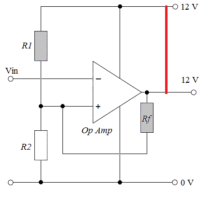
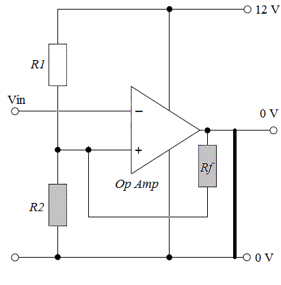
Here is an example circuit using an op amp comparator with a 47 kΩ feedback resistor to the non-inverting input. There is also a potential divider network consisting of two 47 kΩ resistors in series across the voltage rails. The centre point of this potential divider provides a reference voltage to the non-inverting input. This reference voltage establishes the upper and lower threshold limits, and they are two separate values. The trick is to understand that the reference voltages change because they depend upon the state of the op amp output. As you can see, the input to this circuit is inverting, because this is an inverting Schmitt trigger, therefore Vout will always be opposite to Vin. When the input signal crosses the high threshold, the op amp output swings to ground potential 0 V. When the input signal comes back down to cross the low threshold, the output swings to the positive voltage rail, +12 V.
When the op amp output swings between ground and positive rails like this, the feedback resistor essentially connects in parallel with one of the resistors in the potential divider network.

Hence, when the output is +12 V the resistor Rf is effectively in parallel with the resistor R1. Therefore, the total resistance across R1 becomes 23.5 kΩ.
Using the parameters R1=23.5 kΩ, R2 = 47 kΩ, and V=12 V, plug it into the potential divider formula to get the following.


When the output is 0 V, Rf is effectively in parallel with resistor R2. Therefore, the total resistance across R2 becomes 23.5 kΩ.
Using the parameters R1=47 kΩ, R2 = 23.5 kΩ, and V=12 V, we plug them into the potential divider formula to get the following.

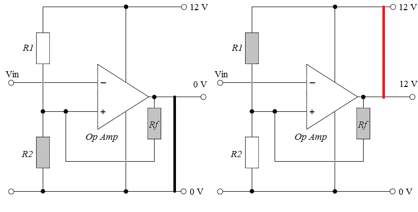
Animation

Although the connection occurs internally through the operational amplifier, you can imagine it like this to make it simpler to understand how the feedback resistor ends up in parallel with the other two. Consequently there are two different reference (and therefore threshold) voltages as shown by the calculations.