RIAA Utilising TA7325 Option 1
This RIAA equalisation circuit for magnetic cartridge uses the TA7325 IC in SIL package. An advantage of this IC and circuit is that it operates on a single rail, and therefore the board layout is almost symmetrical enabling the constructor to build it rapidly. This IC operates on wide range of voltages from 7 V to 18 V, and works fine with a 9 V battery, hence you will be able to test your circuit with battery if you do not have a suitable power supply.
This particular circuit is used in the Aiwa PX-E800 turntable with a magnetic cartridge, and it has extremely good performance. I have built this circuit a few times and have always been impressed with the sound quality and stability. This is one of my favourite circuits as it is very simple and elegant with minimal component count. If you get some high-end components, then the build and sound will be high quality.

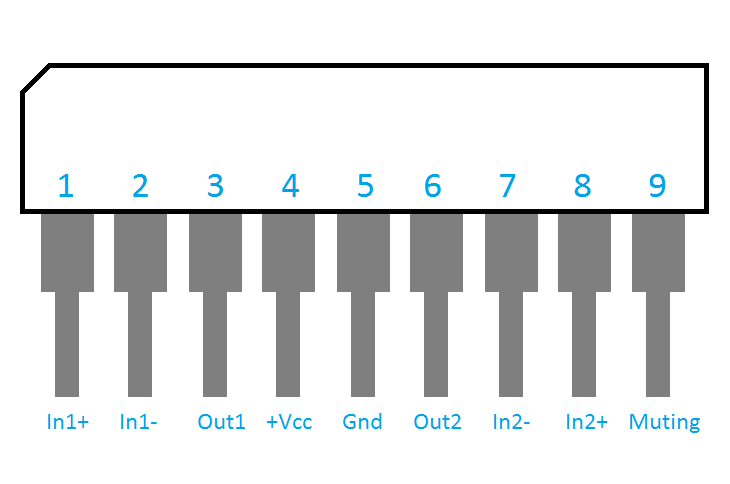
As you can see from the pin out, the operational amplifier pins within the TA7325 are almost symmetrical, which allows us to make an almost perfectly symmetrical board layout for the stereo channels.
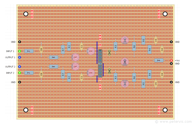
Component Layout


This particular circuit and layout is option 1 as I also have option 2 which is another RIAA circuit based on the Toshiba documentation. This circuit has fewer components and also works extremely well.
Component List
| Type | Part Number | Value | Description |
| Resistors | R1 | 470 Ω | Metal-film, 1/4-watt, 1 % |
| R2 | 47 kΩ | Metal-film, 1/4-watt, 1 % | |
| R3 | 470 Ω | Metal-film, 1/4-watt, 1 % | |
| R4 | 390 kΩ | Metal-film, 1/4-watt, 1 % | |
| R5 | 27 kΩ | Metal-film, 1/4-watt, 1 % | |
| R6 | 1 kΩ | Metal-film, 1/4-watt, 1 % | |
| R7 | 100 kΩ | Metal-film, 1/4-watt, 1 % | |
| R8 | 1 kΩ | Metal-film, 1/4-watt, 1 % | |
| R9 | 220 Ω | Metal-film, 1/4-watt, 1 % | |
| Capacitors | C1 | 100 pF | Ceramic Disc |
| C2 | 10 µF | 25 V, Electrolytic | |
| C3 | 4.7 µF | 50 V, Electrolytic | |
| C4 | 0.01 µF (10 nF) | Mylar Polyester Film | |
| C5 | 0.0027 µF (2.7 nF) | Mylar Polyester Film | |
| C6 | 100 pF | Ceramic Disc | |
| C7 | 4.7 µF | 50 V Electrolytic | |
| C8 | 0.001 µF (1 nF) | Mylar Polyester Film | |
| C9 | 100 µF | 16 V Electrolytic | |
| Semiconductors | IC1 | TA7325P | PDIP |
| Misc | Stripboard | 36-strips × 50-holes | 95 mm × 127 mm |
When you get the non-electrolytic capacitors, make sure they have long leads because many require a lead spacing of 4-holes. Try to get capacitors with the best tolerance your pocket can afford.
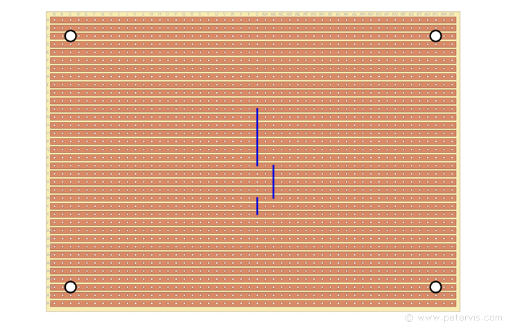
Cut Locations


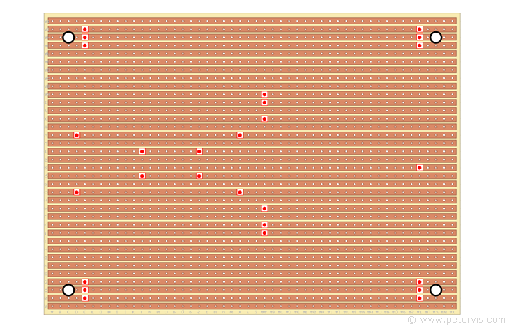
I have designed the board such that the track cuts and links are minimal. They take just a few minutes to make, and then it is a simple matter of installing all the components.
Link Locations


