Scratch Filter Using TL071
This scratch filter circuit uses the TL071CP operational amplifier IC in a low-pass filter configuration designed to attenuate higher audio frequencies. It is useful for removing any surface noise caused by small scratches, and could also be used to remove hiss from tape recorders and FM radio. There is much debate over the best attenuation rate, and although a brick-wall would be very effective, it also cuts off much of the audio spectrum, which may not be desirable. This circuit is a compromise with a -6 dB point at 6 kHz, and attenuation rate of 18 dB per octave.

I particularly like the TL071 operational amplifier IC not only because of the price, but because it has a JFET input providing a very high input impedance. It also has extremely low power consumption, making it ideal for battery powered applications, or for hobby projects where it is necessary to test the circuit with a battery before continuing further to the power supply build. I particularly like the extremely low total harmonic distortion (THD) rating of 0.003 %, which audiophiles in will love as well.
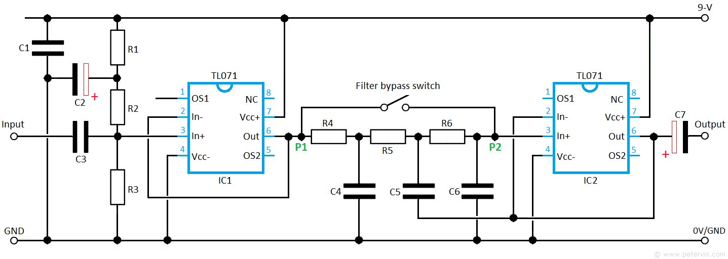
This is an active 3-stage filter circuit with IC2 as the buffer amplifier. In this circuit, C5 forms the bootstrapping function. Notice that in this design, we feed the signal through the non-inverting input, and consequently the output will be in phase and matched precisely. Within the passband of the circuit, C5 has no effect because any signal at its input end is exactly matched at the output end, when it comes out through pin 6. However, outside the passband, the signals will not be matching and that is when C5 comes into play becoming a part of the filter network. An advantage of this method is that this fast introduction of the filtering when needed reduces loss of signals below the cut-off level.
Board Layout


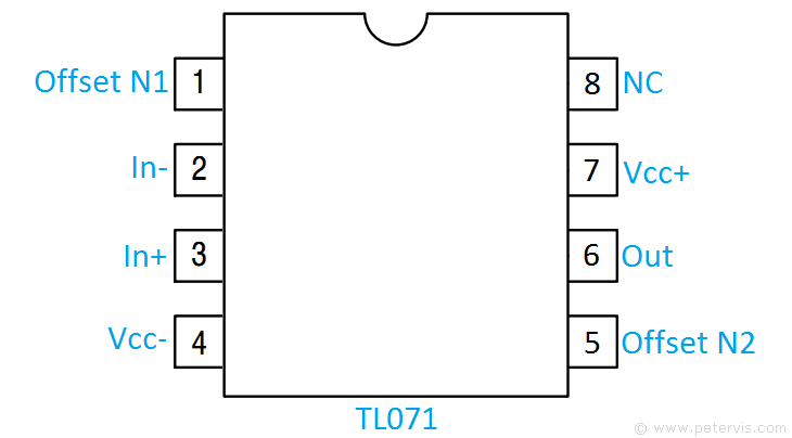
This particular circuit build has many advantages over the others. Firstly, it is very simple to build as the TL071CP is a simple 8-pin IC, where pins 1 and 5 are unused. It is also one of the cheapest ICs (10 for around a pound at auction sites), making it very desirable for the hobbyists’ pocket. You will also be glad to know that this circuit operates over a single supply rail of 9 V, and could be powered by a single 9 V battery as the current consumption of the IC is very low of a few milliamps. The build I have shown here is on nice and large strip boards, which were very cheap and easy to acquire thereby, making it very simple for a beginner to construct.
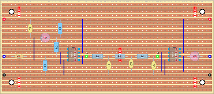
For this filter build, I am using those very cheap strip-boards found in auction site. They have 24-tracks and 56-holes per track, and I managed to get a pack of five for around three pounds. All I had to do was to spray them with an acrylic white paint so the components could be seen clearly. These are nice large sized boards so you do not have to cram your circuit build, and there is plenty of space for the mounting holes as well.
Cut Locations


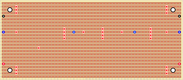
This is the same board flipped over along the horizontal axis. This image is useful if you need to know where to cut the tracks.
Component List
| Type | Part Number | Value | Description |
| Resistors | R1 | 2.2 kΩ | Metal-film, 1/4-watt, 5 % or better |
| R2 | 100 kΩ | Metal-film, 1/4-watt, 5 % or better | |
| R3 | 100 kΩ | Metal-film, 1/4-watt, 5 % or better | |
| R4 | 1.8 kΩ | Metal-film, 1/4-watt, 5 % or better | |
| R5 | 1.8 kΩ | Metal-film, 1/4-watt, 5 % or better | |
| R6 | 1.8 kΩ | Metal-film, 1/4-watt, 5 % or better | |
| Capacitors | C1 | 100 nF | Polyester, 5 % or better |
| C2 | 100 µF | Electrolytic, 16 V | |
| C3 | 470 nF | Polyester, 5 % or better | |
| C4 | 33 nF | Polyester, 5 % or better | |
| C5 | 47 nF | Polyester, 5 % or better | |
| C6 | 3.3 nF | Polyester, 5 % or better | |
| C7 | 10 µF | Electrolytic, 25 V | |
| Semiconductors | IC1, IC2 | TL071CP | PDIP |
| Misc | Switch | SPST | Optional |
| 24-tracks × 56-holes per track | 14.5 cm × 6.5 cm |
