STK465 Diagnostic and Replacement
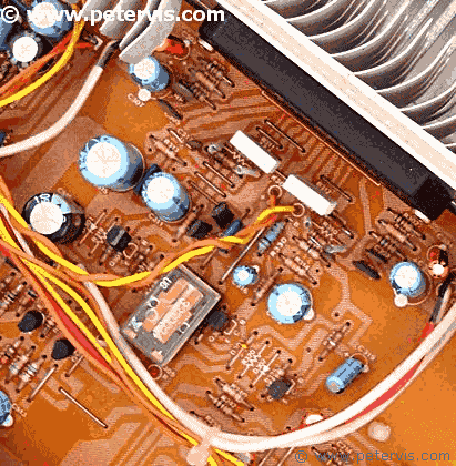
Many had tried and failed... From the looks of the fresh soldering, the relay was a point of focus for whoever had it previously. Obviously, this amplifier had been in the hands of "specialists"; the type of that takes the relay out and cleans the contacts. If that does not fix it then nothing will... Honestly people, leave the relay alone! Carefully, step away, from the relay :-)
Being an experienced engineer with considerably more experience, I decided to turn the winds of fortune around for this amp. Checking the internal fuse with a continuity meter revealed that it was fine. A PAT test indicated that the amplifier was safe to work with. I performed a cursory visual check of the power supply and it was OK. I powered up the unit and the main display lights lit but there was no sound from the test speakers. I double-checked the settings to make sure that I was feeding the signal to the tape input RCA socket, and that the amplifier was indeed set for tape input. It was all correct there as well.
The main transformer is centre tapped for a split voltage supply, hence I checked the AC current and I was getting around 40 V AC at each end of the centre tap, which is about right for an amplifier like this. The main capacitors seemed fine; there was no bulging or leakage, or excessive ripples. I checked the DC voltage across them and I was getting +38 V and -38 V DC, which seems about right.
Tracing the voltage rails at the power supply section revealed that they connected directly to the STK-465 amplifier chip. I am not familiar with this chip but obviously, this chip uses split voltage rails. After a little head scratching, and switching the amplifier ON and OFF, I noticed, the relay was not making any kind of noise. There should normally be the click of a relay when the amplifier powers up. I started tracing the relay coil circuit, which led to a Darlington driver pair. At this point, I realised that this is what a "specialist" in the UK would do... I was clearly on the wrong trail and since I was working without a circuit diagram, I decided to end further investigation of the Japanese state-of-the-art protection mechanism. If there was any kind of fault, it is always usually due to human-error.
Seconds Away...

After a hot cup of Earl Grey, some of the brain cells came back for another round of wrestling... The relay is obviously there to protect the speaker coils from burning out. The relay will not engage if the voltage at the output is incorrect. The pole contacts on the relay are clearly marked on the PCB so I decided to trace where they went and discovered that they connected to what looked like the left and right channel outputs on the amplifier chip.
What I really needed was a circuit diagram, but I figured even a STK-465 Pinout would do. I found some information of the chip on Google. It had a partial unclear example circuit, however, all I wanted to know was which the output pins were. It indicated that pin 7 and pin 10 were the channel outputs. Joy! At least that bit of my deduction was correct! In addition, I have one solid fact to work with.
Without any signal at the RCA inputs, I decided to check the voltage at the output pins. Pin 10 was showing no signs of life; it was dead at 0 V which was unusual however, pin 7 was +37 V DC. Obviously, that did not seem right. Clearly, one channel within the chip was short. In particular, one Darlington pair at the output stage within the STK chip must be short, and feeding the full rail supply to the speaker! In such a condition, the speaker protection mechanism will prevent the relay from energising.
Pin 10 being 0 V is also a little strange, as one would expect a tiny amount of dc offset voltage at the output, hence, I reckon the other channel must have an open Darlington transistor, based on the information I have.
Definitely, the STK amplifier chip had failed. That seemed logical to me based on the facts and the information I gathered. The way this amplifier works is that a protection mechanism senses the DC voltage on the output pins, pin 7 and pin 10 of the STK-465 chip. If the voltages are within normal parameters then it engages the relay and the output pins connect to the speakers.

"Elementary my dear Watson!"
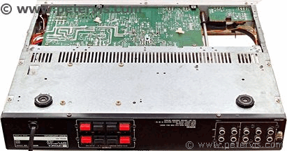
Without a circuit diagram, and with some basic deduction and logic, it was possible to diagnose the fault. But then again, I always make it look easy, and it appears even easier when I explain the deduction. A quick check on eBay for a replacement STK-465 chip revealed that a seller in China was selling one for a fiver. Hence, I ordered one, and temporarily stored away the amplifier until the replacement part arrived.
In the following sections of this article, you can see the replacement chip installed. Once installed, the amplifier worked perfectly. I checked the DC bias and offset and they were perfect and did not require calibration. The sound quality from this golden oldie is wonderful. It has a noticeable bass and treble, and provides a clear and creamy sound. I think that the sound quality is far superior when compared to the modern DSP based receivers.
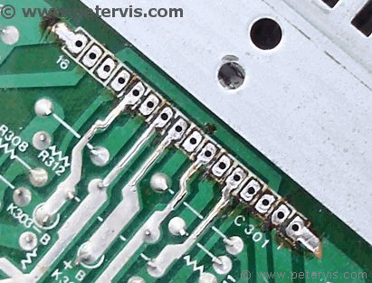
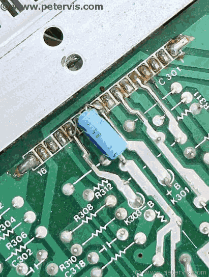
As you can see here, I have desoldered the chip and cleaned the pads with some no clean desoldering braid.
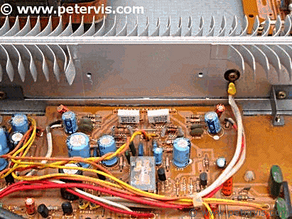
I removed the chip and cleaned away the 30-year old thermal paste. Cleaned all the surfaces and applied a new high performance thermal compound.

As you can see, the new chip fits properly and bolts to the heatsink.
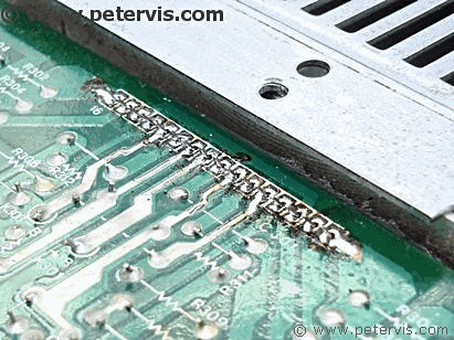
Double check to make sure that all the pins have come through, before soldering starts.
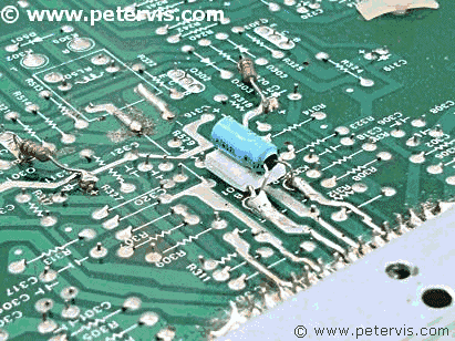
This capacitor requires relocation to a better place, as it is crowded near all the pins.
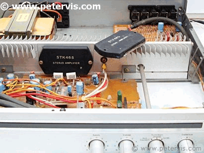
New chip has been fitted and the job well done!
This Article Continues...
Optonica SM-4100Optonica SM-4100 Inside Look
Optonica SM-4100 Metal Chassis and PCB
Optonica SM-4100 Controls
STK465 Diagnostic and Replacement
Optonica SM-4100 Back Sockets
Optonica SM-4100 Input Selector Board
Optonica SM-4100 Power Supply
AN6551F
