Sony STR-DB2000 Protector Code 11
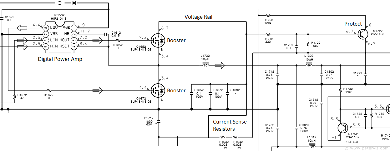
In order to understand some of the protector error messages you need to understand the power output stage of a typical channel. As you can see from a typical channel, the digital power amp drives the booster transistors SUP18N15-95. The voltage rail for the final stage is always through a pair of current sensing resistors in series, and for this particular channel, it is R1632, and R1642, which are 0.025-Ω in value. In the event of a short, these resistors go open thereby isolating the power rail, and when that happens, the protect detection transistor Q1722 detects a change in condition at the base junction which connects to the power rail through R1712.
Protector code 11 indicates irregular current to the speaker terminals, which is when the current is excessively high enough to damage the speakers, or excessively low and outside normal parameters. The first step is to power OFF, disconnect the speaker terminals, and then try again to see if the error happens again. If the error keeps repeating then check the power output transistor "booster" or its associated current sensing resistor.
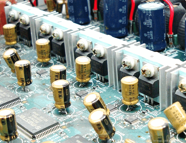
With the amplifier taken apart, I gained access to the D-AMP board. Unfortunately, it is not possible to take voltage readings without the PSU board. The only way to diagnose the fault was to compare the junctions of the 14 MOSFET "booster" transistors. Since the channels are identical, shorts and opens are easily recognised.
For diagnosing, I simply used the diode continuity setting on my cheap Digital Multimeter. It also has an audible buzzer, which is very useful, because you do not have to look at the display reading. With one of these, it is possible to compare looking for opens and shorts very quickly. Since all seven channels are electronically identical, one would expect the MOSFETS to conduct in the same way between their terminals.
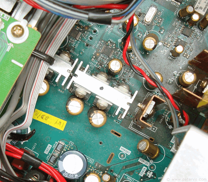
I managed to find two MOSFETS on different sides of the heatsink (back-to-back) that were showing a hard short between all of their terminals. The rest of the transistors seemed fine. Looking closely at the nearby components I also noticed an SMD resistor that had blown in the same part of the circuit as the transistors. It was a Dale 025F, which is a 0.025 Ω / 1 W fuse resistor chip. There are two of these in series providing a voltage rail to the booster drive. If the transistors go short, then these resistors blow isolating the voltage rails from any damage. Each channel has its own pair of fuses like these to protect the voltage rails.

Replacing the pair of shorted MOSFET transistors and replacing the open SMD fuse resistor ought to go a long way to fixing the amp and therefore I ordered the necessary parts. The transistor pairs for each channel are oriented back to back on the heatsinks. As you can see, there is very little space to work with due to the electrolytic capacitors situated nearby.
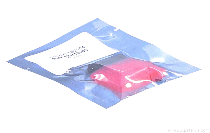
I managed to get a new pair of MOSFET transistors for a fiver on eBay and they arrived all the way from China. They seem to work fine. Being MOSFETS, they are very sensitive to static damage, and therefore they arrive in this anti-static silver bag.
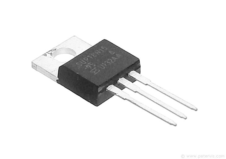
Here is a photograph of a new MOSFET transistor. The one required here is in a TO220 package.
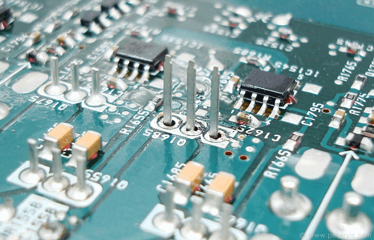
In this photograph, I am preparing to solder the new MOSFET transistor onto the PCB. I am using my Antex Vintage Soldering Iron SK1 Kit. The tracks on this board are very delicate and I kept the temperature to a minimum. It was just enough to melt the solder to get the job done.
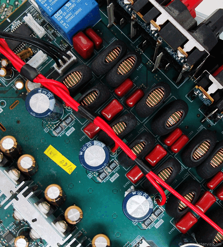
This image shows the current sensing SMD resistor pairs next to the large blue electrolytic capacitors.
Sony Protector Code Error Messages
Sony amplifiers can show a number of error messages, related to the electronic protection of the amplifier from damage.
Protector Error Code 12 indicates that the amplifier has overheated. If the ventilation holes on the top of the amplifier are blocked, then this condition could occur. There is also the possibility that the speaker impedance is too low, or too many speakers connected to s single output. To clear this condition you need to leave the amplifier to cool.
Protector Error Code 13 indicates that the voltage regulators in the power supply section have overheated. Switch off the amplifier and allow it to cool. Make sure there is adequate ventilation, and air flow within the amplifier.
Protector Error Code 21 indicates that there is a transient DC voltage across the speaker terminals. This may be because the input level is too high causing signal clip. The amplifier automatically switches off to protect the speakers.
Protector Error Code 22 indicates that there is a fault within the switched mode power supply. In particular the fault is within the +B voltage rails. Switch OFF the amplifier and check the speaker terminals for shorts.
In all eventualities, it is better to first disconnect the speakers from their terminals and allow the amplifier to cool by switching it OFF. Switch ON the amplifier after a few hours to see if the error condition has cleared.
Decode Error 01 indicates that the digital stream cannot be decoded. You need to go into the Customize Menu of the amplifier and set the PCM to Auto.
This Article Continues...
 Sony STR-DB2000 Review
Sony STR-DB2000 Inside Look
Sony STR-DB2000 Protector Code 11
Sony STR-DB2000 Power Supply Board
Sony STR-DB2000 Back Panel Connections
