Colpitts Oscillator Design
The Colpitts oscillator is a type of high frequency oscillator consisting of a LC tank within the feedback loop of a class-A common-emitter bi-polar junction transistor (bjt) circuit. The tank circuit usually consists of a pair of capacitors in series joining to an inductance coil. The simplest type of bjt circuit consists of a shunt-fed LC tank as shown above.
For this oscillator to start, the voltage gain must be equal to or greater than the Barkhausen criterion described by the following expression:

In this expression, Av is the amplifier voltage gain, and beta is the feedback ratio. Usually engineers forget to use this part in their calculation, which is why their circuits do not work!


In this type of tank circuit the output voltage appears across C1 and the feedback voltage across C2 therefore, we get the above expression for beta:

This means that for the oscillator to start, the voltage gain Av must satisfy the above condition in terms of capacitance ratios.

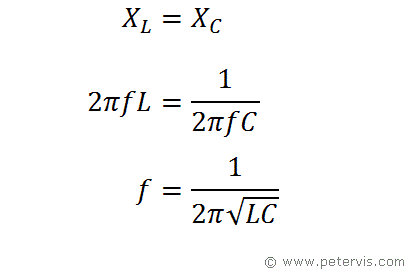
The antiresonant frequency of the Colpitts oscillator occurs when the reactance presented by the inductance, and total capacitance, are equal.

This is where C is the total capacitance consisting of C1 and C2.

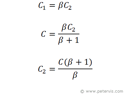
Since the ratio of C1 and C2relate to beta, we can get an expression for C2 in terms of C and beta. This formula helps to calculate individual capacitor values with proper ratios. If these ratios are not correct, then your oscillator will not start, hence this part is extremely important.

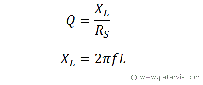
A high Q value is extremely important in this circuit as it maintains stable oscillations and produces near perfect sine waves when the transistor is driven beyond class A. In this formula, XL is the resistance of the coil at the resonant frequency, and RS is the DC resistance of the coil.
Related Articles
Colpitts Oscillator DesignColpitts Oscillator using Op Amp
Colpitts Oscillator Calculator
