NAND Gate LED Flasher Using CD4011B IC
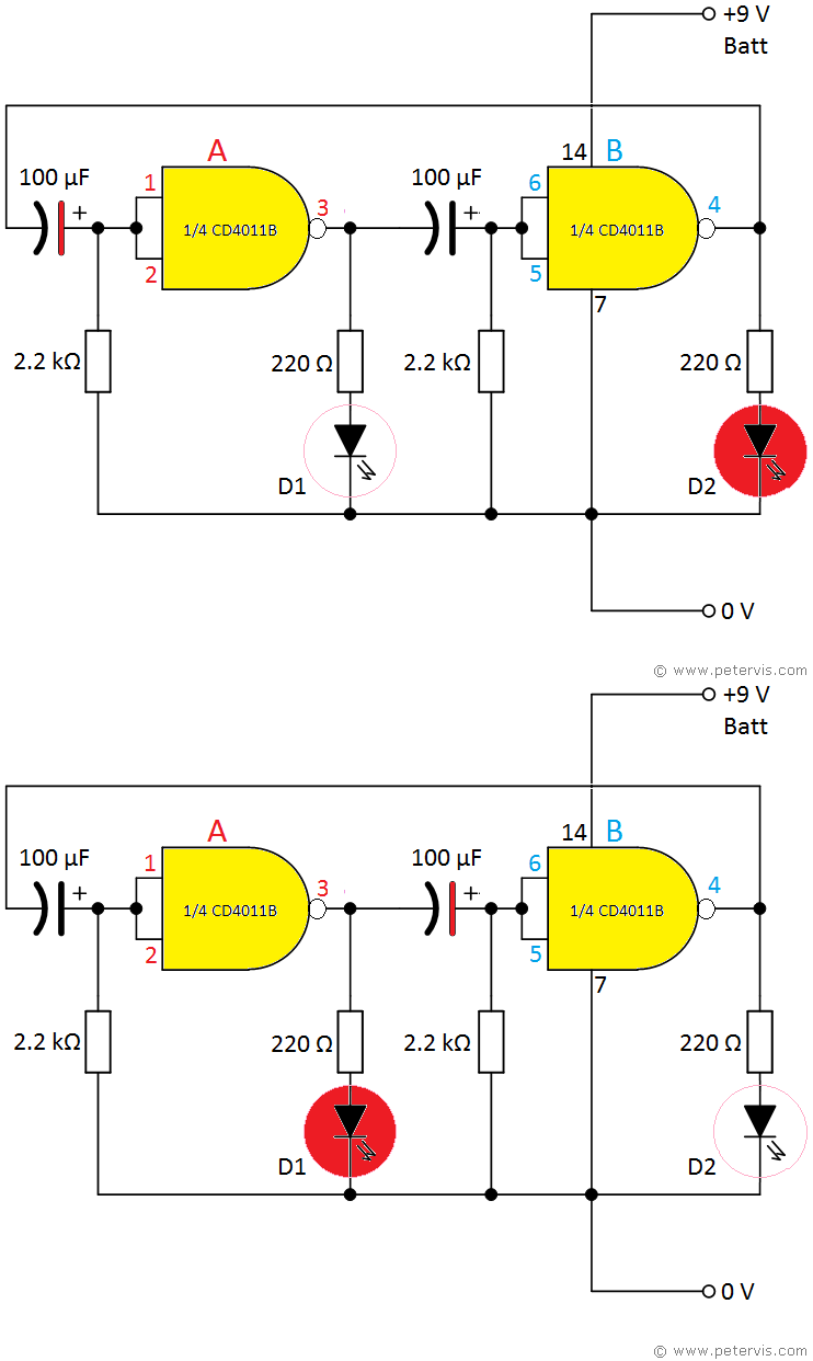
This is a NAND gate LED flasher circuit using the CD4011B IC. An advantage of using this IC is that it has a supply voltage range of 3 V to 18 V, which enables you to power the circuit with a PP3 9 V battery. The CD4011B has a different pinout to the SN74LS00, and therefore the circuit is different, but the good thing is that both ICs are 2-input quad NAND packages. The gates and the circuit work in precisely the same way; therefore, if you need more information, then you should consult the other article as well. The links are at the bottom at the page.
Keeping in mind that these are NAND gates, when the input is logic 1, the output is logic 0, and vice versa, because joining both inputs of the gate makes it behave as an inverter. Since the output of one gate connects the input of the other, when one gate produces logic 1 at the output, the other produces logic 0 at its output.
The input to each gate has a 2.2 kΩ pull-down resistor establishing logic 0. However, it is not a very hard pull-down because of the large value, and if we were to introduce a very small positive voltage at the input then it would register that as logic 1 because these CMOS NAND gates require as little as 0.5 V or more to register logic 1 (when supply voltage is 5 V).
The pull-down resistor establishes logic 0 causing the led to light, whilst a small amount of positive voltage from the capacitor anode establishes logic 1 causing the led to go OFF. However, as you can see, we need to charge the electrolytic capacitor in reverse, if we need a positive voltage at the input of the gates. Ideally, a non-polarised capacitor would work better, however, since the amount of positive voltage required is so small, a polarised electrolytic capacitor works just as well for this low voltage experiment. This is because when you charge a polarised capacitor in reverse (at very low voltages of course) they still store a very small amount of charge, and a few volts are all we need for logic 1 to be registered.
This is a great circuit that works well and ideal for experimentation. You could try non-polarised capacitors. Alternatively, perhaps make your own by connecting the cathode ends of polarised capacitors together.
Please note that extremely intelligent professors have tried, tested and verified this circuit, and you will see the LEDs blink.
CD4011B

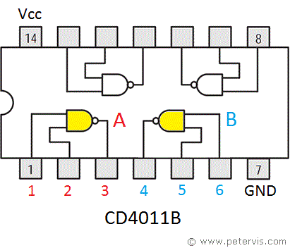
Here is the pinout for this IC. Compared to the SN73LS00, only two gates are facing different way. Both ICs are good and currently available cheaply therefore, the option is simply dependent upon your preferred powering method.
Related Articles
NAND Gate LED Flasher Using SN74HC00N ICNAND Gate LED Flasher Using CD4011B IC
Circuit Experimentation
