Raspberry Pi Analog Input Circuit

The Raspberry Pi analog input circuit is a simple circuit for testing the MCP3002 Analog-to-Digital Converter (ADC) IC. Once you have the SPI pins connected, you may need to test the circuit by supplying a signal to the ADC.
One of the basic principles of an ADC is that the input signal must be within the same range as its power rails. This is not always the case with more complex ADC packages; however generally smaller packages follow this rule because they use the power rail as a reference voltage for their internal ADC calculations.
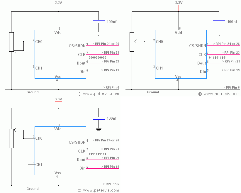
In this circuit, a 10 kΩ potentiometer creates a simple voltage divider circuit, where one end connects to the ground and the other end to the 3.3 V rail. By setting the wiper to any position, you can achieve any voltage in the range between 0 V to 3.3 V, which is a valid input to the ADC channels CH0, and CH1.
Resolution
This IC provides a 10-bit resolution to represent any analog value. When the wiper is set to the extreme ground end the input voltage will be at 0 V and therefore the data out, observed at pin 6, will be binary "0000000000". However if you were to set the wiper to the other extreme end thus feeding 3.3 V at the input then the digital value observed at pin 6 will be binary "1111111111" which is 1023 in decimal.
Potentiometer
Almost any potentiometer of around 10 kΩ value should work for the test circuit and it could be a panel mount one or just a small preset. A hobbyist usually has a couple in the recycled component box. However if you must buy some then I saw some affordable ones on eBay. They had a bag of five for about two pounds.
This Article Continues...
How an Analog-to-Digital Converter ADC WorksRaspberry Pi ADC: Analog to Digital Converter Chip MCP3002
Raspberry Pi Analog Input Circuit
Raspberry Pi LDR Light Sensor Circuit
ADC Circuit: Raspberry Pi Analog Input Circuit on Breadboard
MCP3002
Raspberry Pi SPI
Raspberry Pi Pinout