Build Your Own Breadboard Power Supply

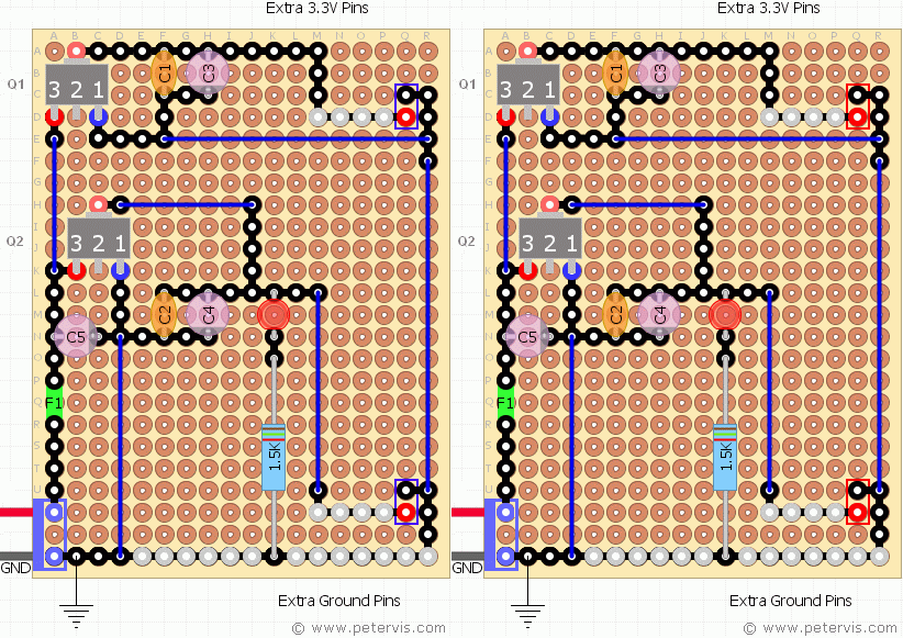
Building your own breadboard power supply module is very simple. This article shows a homemade circuit, which could be useful as a GCSE school project. The circuit uses the AMS1117 series voltage regulators, which are one of the best and cheapest currently available. All DIY hobbyists will have some at home. If you want to know how to make a breadboard power supply cheaply then this is probably the best and the lowest cost project that I made that anyone can follow. This homemade project will produce regulated 3.3 V and 5 V rails. Consequently, this build uses a pair of header pins providing power and ground on each side of the board. The module will plug-in on a conventional solderless breadboard to provide power.
Building the Circuit Board
This homemade project is almost like a kit and uses a standard size prototyping board that is readily and cheaply available on eBay at a quantity of 10 for around one pound. You should read the following pages for more information on using it.
PCB Prototype Matrix Board 50 mm × 70 mm
A Soldering Guide for Beginners, Kids, and Electronics Students
AMS1117 Voltage Regulators
The AMS1117 is a high efficiency low dropout voltage regulator manufactured by Advanced Monolithic Systems. It operates down to 1 V making it an ideal component to be used with portable battery applications. Hence, if you want to create 5 V and 3.3 V rails, then this regulator is a good choice for the price. It has a maximum current handling capability of 1 A and can operate on a maximum input voltage of 15 V. The following page has more information.
The regulators for this project require soldering on the copper pad side because it is an SMD. This is why the terminals are marked 3, 2, 1. If you are new to SMD then this is probably the nicest component to start out with because it is in a SOT-223 package, which is nice and large enough to work with.
Capacitors
For the electrolytic capacitors C4 and C3, you can use nice high values such as 220 µF or 470 µF to compensate for those surges when you are plugging wires and components on the breadboard.
Capacitor C5 can be a nice high value of 1000 µF if your adapter power supply is not very smooth and you have some spare capacitors of course. All the electrolytic capacitors used in this project must be rated 16 V or higher. Capacitors C1 and C2 are ceramic disc types, and they can be 47 nF in value for filtering noise on the power planes.
Components
Fuse F1 is a polyfuse type, just to be on the safe side. However it will exhibit a voltage drop, hence its use is contingent upon your application and simultaneously its performance.
For the LEDs, I am using the high efficiency types with a forward voltage drop of 1.7 V, and forward current of 0.002 A. A series resistance of 1.5 kΩ is required for this application. Please refer to the following article for more information.
Power Sources
If the breadboard project is to power one or two CMOS logic chips then an adapter of 200 mA or more will work fine.
A CMOS logic IC usually requires around 10 mA on average to operate. Moreover, if you are using one of those small breadboards, you can only at best fit two or three chips on them. Hence, for any simple logic gate experiment a small power source will work fine.
For the input socket, I am using a screw terminal block, which is useful if you wish to use a battery power source, then you can attach the battery leads from the battery holder instead.
Testing the Module
Thoroughly go over your circuit making sure that there are no mistakes in the connections. Check for solder splashes; check each component and its connection before applying power to it.
When testing it for the first time you should use a low voltage of around 6 V and a very low current. Measure the output voltages using a digital meter. You should get +5 V and +3.3 V at the outputs. If you are getting these voltages then congratulations, you can now use the circuit to power your breadboard project. Perhaps the first project should be blinking some LEDs using a Darlington driver chip.
Total Cost
All the components came from eBay, many of which came directly from China. I managed to buy in small quantities of five for a pound. I also used recycled capacitors, and resistors, and managed to make it for under a fiver, with some extra spare components left over for the next project. Obviously, if you were to buy in larger quantities such as 30 of each then the total price can come down to around a pound for each build, which is pretty good value in this inflation climate.
This Article Continues...
Breadboard Power Supply GuideBuild Your Own Breadboard Power Supply
YwRobot Breadboard Power Supply
Breadboard Power Supply USB
