FQPF 7N80C MOSFET Test
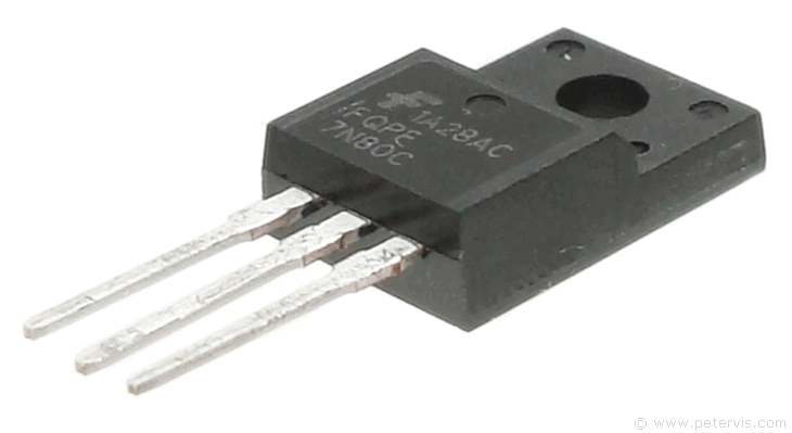
MOSFETS failure is very complicated to diagnose and it is always best to remove it from the circuit first when checking it with a meter. These transistors can fail in many ways because if you can imagine, it switches 400 V very fast, therefore one obvious type of failure is a complete short of all the junctions. A simple continuity/buzzer test would clearly diagnose this, and this is the simplest to detect because in a good transistor there are no two junctions that would conduct so hard in both directions. However, a more complicated failure to diagnose is an open circuit in the transistor and for this, one has to remove it from the board for testing.
A new replacement transistor usually comes in an anti-static bag for a very good reason. The gate junction of a MOSFET is very sensitive to voltage, and high electro-static voltages will definitely destroy it, therefore take all the ESD precautions possible!
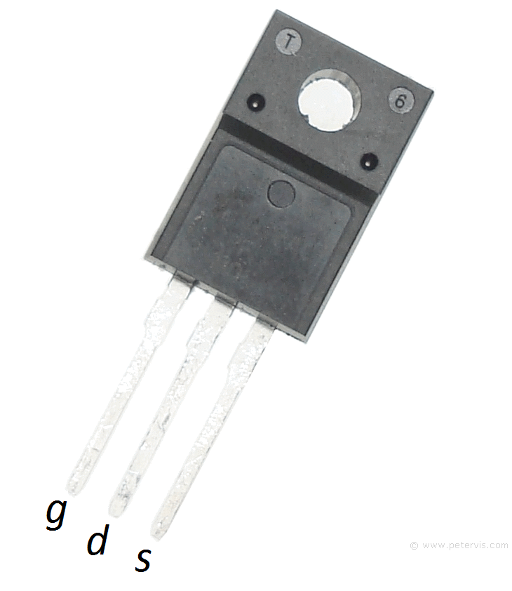
To test the FQPF 7N80C, I used the diode test function of my multimeter. On that function, it also has a buzzer function for continuity which is often a useful indicator. In a good transistor only the drain and source pins will conduct because of the internal protection diode that exists between these two pins. With the red probe on the drain and the black on the source, it does not conduct. However, with the black probe on the drain and red on the source, it conducts and the forward voltage measured was 461-mV approximately. If you compare this with your old one, and get any other value, or it conducts in both directions, then the MOSFET is likely faulty.
Another good MOSFET action that is useful for comparison is how well it switches. If you connect the black probe on the drain and the red on the gate pin, the voltage that the meter passes to the gate junction causes the transistor to begin conducting for a small amount of time. When you connect the red probe to the source pin, leaving the black probe connected to the drain, the meter will buzz (if you have the buzzer function). It remains conducting like this for a small time so you need to be quick transferring the red probe. If you do not get this hard switching action, then it is likely faulty. On my faulty one, this action did not happen and instead all that the meter displayed was the forward voltage of the internal diode. I tried it a couple of times, switching the red probe very fast, but it seemed that it was not switching and something inside was open circuit. Hence this was a possible clue that this transistor may be faulty.
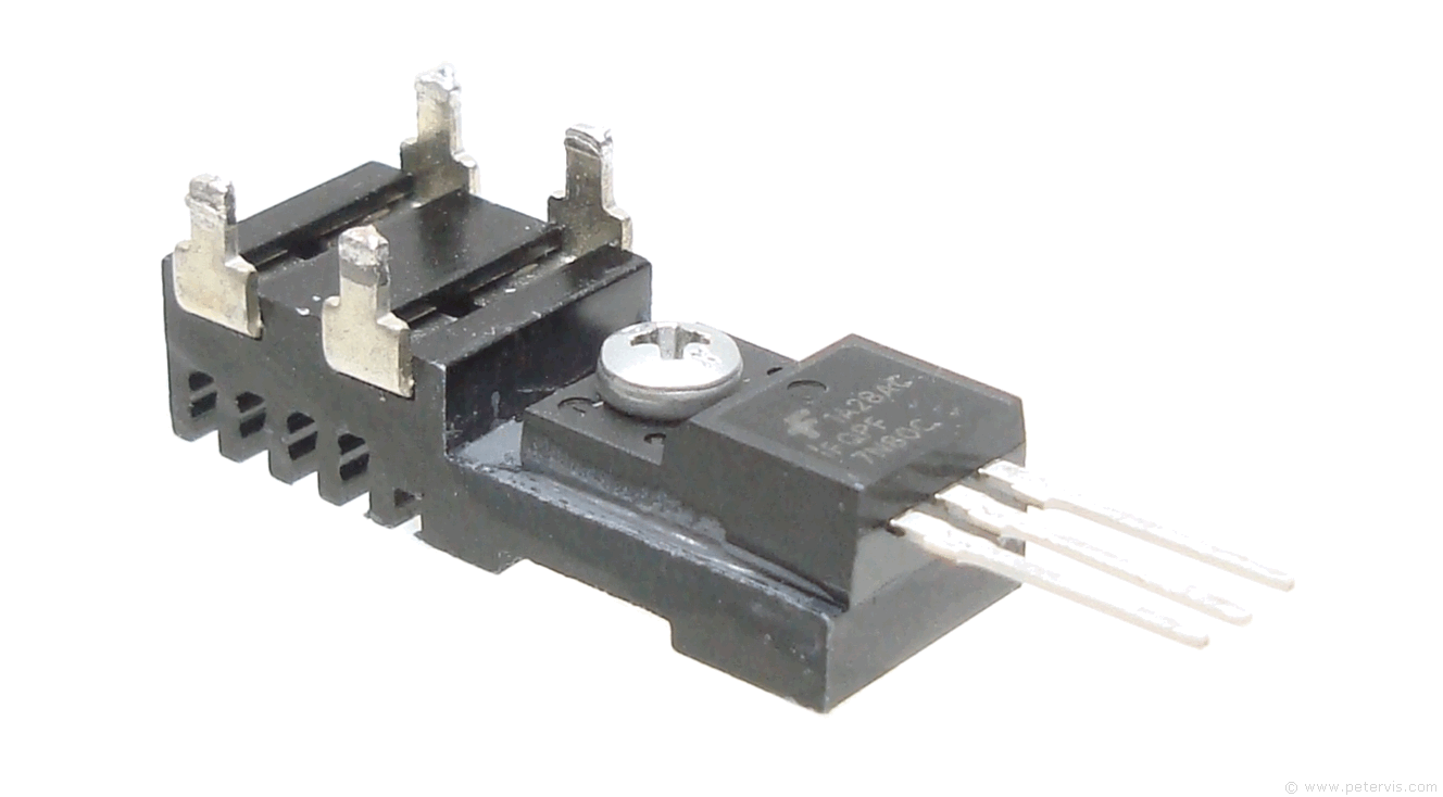
When you install a new MOSFET be sure to minimize the level of heat to its pins. In this application, the transistor first has to be fitted to the heatsink with some compound applied to its back. Annoyingly, the heatsink also requires soldering to the board with the transistor on the underside. It is a shame they did it this way as it makes servicing very difficult. What they should have done was use a heatsink that remains soldered to the board with the transistor fitting to it from the top. This way, there would also be more airflow with the transistor on the outside.
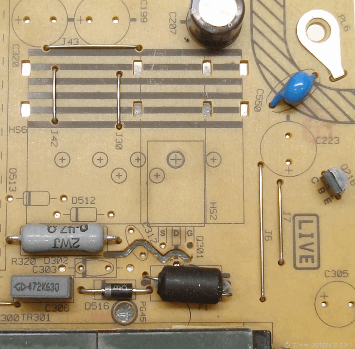
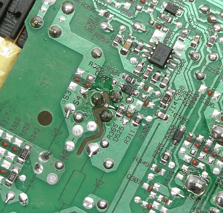
Looking at the printing on the board, it indicates that there were other versions with a much larger heatsink, so perhaps this board is the cheaper version with a smaller heatsink. As you can see, there is no scorch marking on the board, as this television had very little use.
Here is one that I soldered.
This Article Continues...
17IPS20TV with 17IPS20 Blinks and Does Not Start
FQPF 7N80C MOSFET Test
MP3394/MPS3394S LED Driver Diagnostic
17IPS20 Repair