Resistors in Series

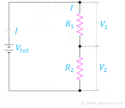
Resistors joined in series form a series network whose equivalent resistance is the sum of the individual resistor values. A series network usually forms a potential divider (PD) network, because the current is the same through both resistors; however, the voltages across them are different. Hence, each resistor forms a voltage drop as a PD would.
If you are a beginner, some questions running through your mind will be, "Can you put resistors in series?" Alternatively, perhaps you may be thinking, "Do you add resistors in series?" Therefore, this bite size article provides very simple explanations.
Calculator
Here is a simple calculator to add two numbers. The units are in ohms of course.
Formula

Resistors in Series vs. Parallel
The difference between resistors in series and parallel is noteworthy. In series networks, the current flowing through the resistors is the same; however, each resistor has different voltage across it. The total voltage is equal to the sum of the individual voltage drops across the resistors. Kirchhoff's second law of voltage would apply here because the total voltage in the loop is equal to the sum of all the voltage drops.
In parallel networks, each resistor has the same voltage across it; however, the current flowing through them is different. The total current is equal to the sum of the individual currents through each resistor. Kirchhoff’s first law of current would apply here, because the total current entering the node is equal to the sum of individual currents leaving it.
Derivation


The current "I" flows through both resistors R1 and R2.

This expression describes the voltage across resistor R2.

Whether it is Kirchhoff’s Law or plain common sense, the total voltage must be equal to the sum of the individual voltages across the resistors. It cannot be any more or less, because as Scotty in Star Trek always says, "You cannot break the laws of Physics!"
Substituting the previous expressions into this one, we get the larger expression as shown below.

As you can see, the current "I" is the same throughout, therefore we divide throughout by "I" to eliminate it.

Finally, here is the derived formula for resistors in series. You therefore add resistors in series.
Power Dissipation
P = I² × R
This expression describes the power in watts in terms of current and resistance. Since power is directly proportional to resistance, increasing resistance increases power dissipation of the circuit. Therefore, adding resistors in series increases the equivalent resistance, and therefore the wattage of the circuit.
Application
A series resistor is widely used in the field of electronic engineering. It connects with an LED to create the required voltage drop. It also connects with a Zener diode to make a voltage regulator circuit.
Related Articles
Resistor Colour CodeStandard Resistor Values
Ohm’s Law
Resistors in Parallel
Resistors in Series
Delta – Y Transformation Calculator