Gain Control Circuit -- Quadraphonic SQ Decoder

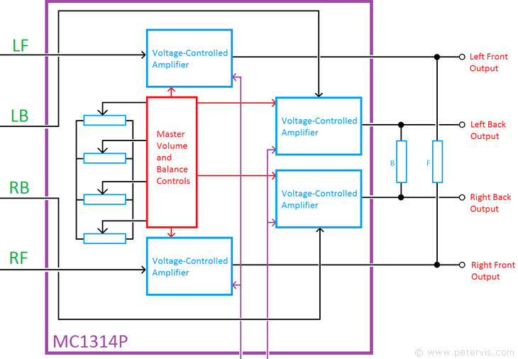
The MC1314P is a gain control and balance adjustment IC for use with the CBS SQ quadraphonic decoder. It consists of four voltage-controlled amplifiers with adjustable gain. By varying the DC voltage using low-cost variable resistors, it is possible to provide master volume, LF/RF, LB/RB, and F/B balance controls. This IC also has inputs to connect to the MC1315P to provide increased front to back separation. This particular feature makes this quadraphonic system highly desirable due to the improved sound separation.
- DC controlled gain
- Four separate audio preamplifiers
- Compatible with MC1312P decoder and MC1315P logic enhancement ICs
Board Layout


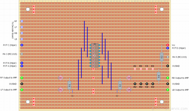
Although there are not very many components around the MC1314AP, I decided to redraw this section of the circuit diagram simply to reorganise the wiring. As you can see, the other two ICs connect to it, and therefore it was vital that there was some form of wiring standardisation between the boards, so it connects together easily.
Channel Blending
Channel blending is achieved by connecting the front channels together with a 20 kΩ resistor (R1), and back channels with 8.2 kΩ resistor (R2). According to the designers, it improves the centre-front to centre-back separation by cancelling the out-of-phase sound components inherent in this type of quadraphonic system. Obviously, this will also have the effect of reducing the separation between the left and right channels; therefore, I have added jumpers J1 and J2 in the build. At first I was thinking of using jumper pins but later found a switch so decided to use that instead.
Component List
| Type | Part Number | Value | Description |
| Resistors | R1 | 20 kΩ | Metal-film, 1/4-watt, 1 % |
| R2 | 8.2 kΩ | Metal-film, 1/4-watt, 1 % | |
| R3** | 910 Ω | Metal-film, 1/4-watt, 1 % | |
| R4** | 560 kΩ | Metal-film, 1/4-watt, 1 % | |
| Variable Resistors | VR1 | 5 kΩ | Logarithmic |
| VR2 | 5 kΩ | Linear | |
| VR3 | 5 kΩ | Linear | |
| VR4 | 5 kΩ | Linear | |
| Capacitors | C1 | 1 µF | Electrolytic, 63 V |
| C2 | 1 µF | Electrolytic, 63 V | |
| C3 | 1 µF | Electrolytic, 63 V | |
| C4 | 1 µF | Electrolytic, 63 V | |
| Semiconductors | IC1 | MC1314P | PDIP |
| Misc | Stripboard | 36-strips × 50-holes | 95 mm × 127 mm |
** If you are using a 6 V regulator, then you will not need these resistors, which form a potential divider network.
The electrolytic capacitors are not so critical and simply provide a dc blocking function. Here you can get away with using something like 1 µF/50 V. I just recently got a bag 100 capacitors for 99 pence on eBay and they are very useful for audio applications like these.
Board Cuts


Board Links


This Article Continues...
Gain Control CircuitGain Board Completed Build
