Programming the 128x64 LCD
Programming the 128×64 range of LCD panels will be very simple once you read this article. In the photograph above, you can see three Chip-on-Board (CoB) package modules on the display PCB. Two of them are KS0108, and one KS0107. There are many LCD modules on the market and their programming is usually the same due to having the same chipset.
The most common question most people ask is how to program the KS0108 LCD, or the 128×64 LCD. How are the pixels organised? How is a byte of data organised onto the LCD screen?
Geometry of the Shadows
The main question beginners, and advanced engineers have is, how are the bits sent to the display physically organised into pixels on the LCD? When you send eight bits of data to the LCD, how is the organisation of this data on the screen at pixel level? I have found that this method is the same for all 128-dot × 64-dot graphical displays, and even those that have different segment drivers.
The Better of the Two KS0108 Halves

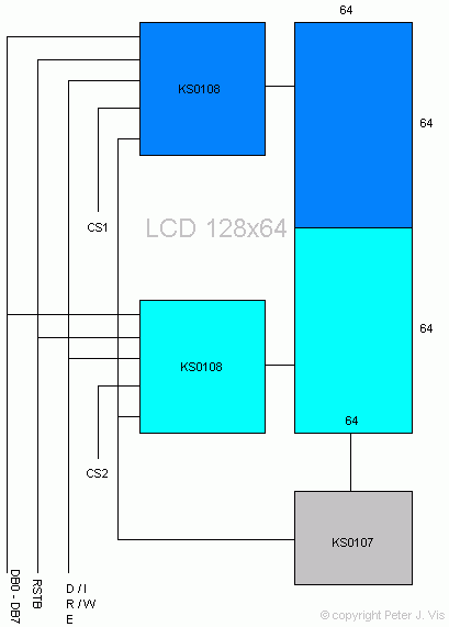
The KS108 is a 64-dot segment driver; therefore two are required to make 128-dot display. From a programming perspective, the LCD screen consists of two individual LCDs, and each receives data individually. CS1 and CS2 allow the programmer to select which chip receives the delivery of the data in the data bus (DB0-DB7). When the chip receives the data, it sets the pixel for its half of the display.
In the diagram above, you can see that each half of the display shares the data bus and control lines, so engineers will not have to consider controlling each half separately, however having two independent halves of the screen to send data to can be a pain. If you need to write a long line of text, you need to keep track of the column number, as well as the number of columns a single character occupies. When you reach column 64 you have reached the end of the first half of the display. This is when one lowers control line CS1 to logic 0, and makes CS2 high to logic 1 so that data in the data bus goes to the second half of the LCD.
Writing a graphics driver for a liquid crystal display that operates in halves can be a little tricky. If you had to draw a circle in the middle of the screen, then at which point in the function would you switch CS1 to CS2. This would obviously be as soon as the horizontal pixel number becomes greater than 64. Hence, any kind of display driver code will need a counter to keep a track of the column number, so you can switch CS1 and CS2 appropriately.
The Pixel Display Geometry

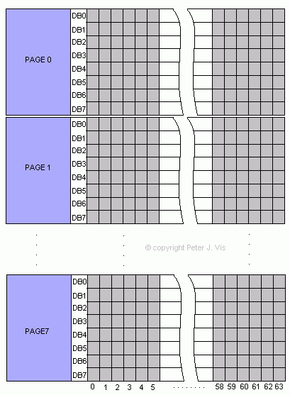
Since both halves operate in the same way and controlled by CS1 or CS2, we only need to look at one-half to see how a byte of data groups into dots.
The first thing to notice is that a byte of data organises vertically filling a column of pixels. The diagram above shows a 64-dot × 64-dot matrix. The columns are simply from 0 to 63 they are not grouped in any way, however the rows are grouped. What is confusingly called a "Page" is simply eight rows forming a group. In addition, to confuse you further; a page is an "X Address" in programming nomenclature. I do not know how these engineers got their degrees...
Since there are eight rows of dots in a page, and there are 64 rows of dots, it does not take a NASA scientist to figure out that there are only eight pages in total for the LCD.
A "Page" is therefore just a group of eight rows. When you send data (8 bits) through the bus, it fills vertically in a single column spanning eight rows, also known as a page.
In addition, you cannot write to only one pixel and ignore the rest. To set individual pixels you have to read back from the LCD what is already there and perform a Boolean mask operation. This is of course extremely simple to implement.
Y Address
The "Y Address" is simply the column number, which ranges from 0 to 63, keeping in mind that we can only work with one half of the screen at any one time. This parameter requires tracking through a counter in your program code.
From the hardware perspective, the "Y Address" is automatically incremented, as the display has internal counter circuitry. When you send the next byte of data, it automatically fills on the next column. From the programming perspective that is a good thing because, you will not have to set the column number through program code when "printing" to the next column. However, you will need to keep a track of it in a variable so that you know when to switch over the CS1 and CS2 control lines and therefore the displays.
How a Byte of Data Fills the Pixels

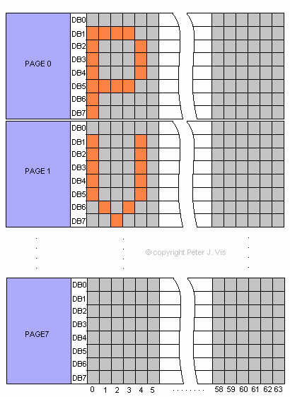
A byte of data in the data bus fills the LCD matrix vertically in a column. One byte of data in the data bus sets the dots marked from DB0 to DB7 in a single column. Once filled, the internal circuitry automatically increments to the next column, for the next byte of data.
The diagram above shows how to display the letter 'P' of the alphabet.
- First, select which half of the screen to use. Make CS1 high for the first half.
- Select the "Y Address", the column number (from 0 to 63) where the first byte of the character will start
- Select the "Page" number to 0, which is the first eight rows of dots on the LCD.
Send the following bytes of data in succession.
- 11111110
- 00100010
- 00100010
- 00100010
- 00011100
- 00000000
As you can see, the bytes are human-read horizontally from right (LSB) to left (MSB) but the data fills vertically on the LCD column from DB0 to DB7.
The y counter is automatically incremented for the next column, so as a result you only have to send bytes of data in succession. However, it is best to keep a counter C++ to keep a track of the column you are on as good practice for the future when you will be writing more than one character.
Note
In this example, each character occupies eight rows and six columns. For each character, we leave DB0 as empty which serves as a character spacing between lines. In addition, we leave the last column empty, which serves as the character spacing between characters.
This Article Continues...
128x64 LCDProgramming the 128x64 LCD
KS0108 128x64 LCD Hardware Control
128x64 Timing and Modes
128x64 LCD Graphics Driver Design
128x64 ASCII Text Driver Design
128x64 Bar Graph