128x64 Timing and Modes

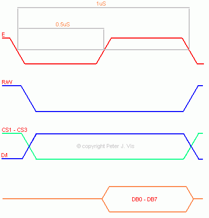
Timing is a very important consideration with these LCD displays, and there is a physical limit to how quickly the display is able to receive data.
The documentation specifies a minimum of 1 µs cycle for the E signal lock and load latch, however realistically it should be more like 4 µs if your circuit is built on prototyping board. Every circuit has different track inductance, and noise, and therefore this value should be appropriate. On my development system, which is built on prototyping board, the minimum I can use is 4 µs, and any less will cause the LCD to display scrambled data.
The documentation of the LCD module contains all the timing diagrams and mode information; therefore, I am only going to show the main aspects of timing which is the "_delay_us(4)".
In normal operation, the LCD is required to change modes between display mode and command mode.
The command mode allows the setting of the page and column addresses, and the data mode allows the display of graphics data.
Writing data - Data Mode
An input register temporarily stores the data in the bus DB0-DB7 before writing it into the display data RAM. The data goes into display data RAM automatically when "E" goes high and then low.
A. Set the data writing mode by setting the D/I pin to logic one and R/W pin to logic zero, achieved by the following code.
1: void DataMode (void)
2:
3: // Set pins for Data Mode.
4: cPort |= (1<<lcdrs);
5: cPort &= ~(1<<lcdrw);
6: }
B. Send the data you want to display to the bus pins DB0 - DB7.
C. The data at the input register is latched at the fall of the E signal (pin 6), so set this to high and then low by clearing it using the following code.
1: void LocknLoad (void)
2: {
3: cPort |= (1<<lcde); // Output: Data Load.
4: // Delay.
5: _delay_us(4);
6:
7: cPort &= ~(1<<lcde); // Latch: Data Lock.
8: // Delay.
9: _delay_us(4);
0: }
The documentation specifies a minimum 1 µs cycle for the E signal lock and load latch, however realistically it should be more like 4 µs, for the reasons described above.
Sending commands - Command Mode
In order to set the column and page registers, the command mode requires setting first.
A. Enable CS1 and CS2, so that both halves receive the commands.
1: cPort |= (1<<lcdcs1); // Enable CS1 and CS2
2: cPort |= (1<<lcdcs2);
B. Set the command mode by setting the D/I (pin4) to logic 0 and R/W (pin 5) to logic 0, as shown by the following code.
3: cPort &= ~(1<<lcdrw);
4: cPort &= ~(1<<lcdrs);
C. Send the command to the bus DB0 - DB7.
D. Set E high and then low as shown in the function LocknLoad () above.
All of these functions are already in my 128x64.c library.
This Article Continues...
128x64 LCDProgramming the 128x64 LCD
KS0108 128x64 LCD Hardware Control
128x64 Timing and Modes
128x64 LCD Graphics Driver Design
128x64 ASCII Text Driver Design
128x64 Bar Graph