LM3914 Resistor Calculator
This LM3914 calculator computes resistor values and shows the working principle behind the formulas. It starts with a simple explanation of how it works, how to use the formulas for a basic bar graph display, and how to transpose the formulas to calculate unknown values. The circuit example shown here is for a simple linear bar graph display that drives ten LEDs. This type of display may be popular for making a battery level indicator to monitor the battery power or a fuel gauge.
As you can see, there are ten 1 kΩ resistors forming a potential divider circuit known as a ten-step divider. This means that ten resistors divide the voltage across the potential divider equally. One end of the potential divider is RLO (R LOW), which usually connects to the 0 V (earth). The other end of the potential divider RHI (R HIGH) is where we usually connect the positive voltage. The designers of this IC have provided a stable voltage source for use with this potential divider. The reference voltage source is an internal circuit that can provide a stable and accurate voltage in the range 1.2 V to 12 V. Therefore, we usually connect Vref Out (pin 7) to RHI (pin 6), which feeds a positive voltage to the potential divider network.
LED Brightness and Resistor R1

Resistor R1, which controls the current to the LED, determines the LED brightness as shown by the formula above.

If we knew the current that the LED requires I LED, then by transposition, we can calculate the value of R1 as shown by the formula above.
Calculating Resistor R2

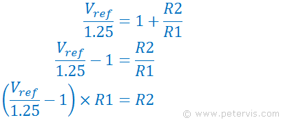
The voltage produced by the internal reference circuit at pin 7 (Vref) depends upon the values of two external resistors namely R1 and R2. For exams, you might have to learn to transpose this formula to find R2 as shown here.

Here are the steps if you were to transpose it.

Here is the formula to find R2, providing you had all the other parameters.
If the input signal (to pin 5) were to range from 0 V to Vi MAX, then it follows that the reference voltage Vref should also be equal to Vi MAX, but limited to the range of 1.2 V to 12 V. Remembering that the reference voltage goes across the internal potential divider, and each step of the divider will be Vref/10-volts providing a resolution of Vref/10-volts per LED. Since we also have the value of R1 (previously calculated), we can find the value of R2.
Related Articles
LM3914 Circuit TutorialLM3914 Resistor Calculator
LM3914 Resistor R1 Calculator
LM3914 Resistor R2 Calculator
Flash ADC Resolution

