3V Germanium Transistor Radio

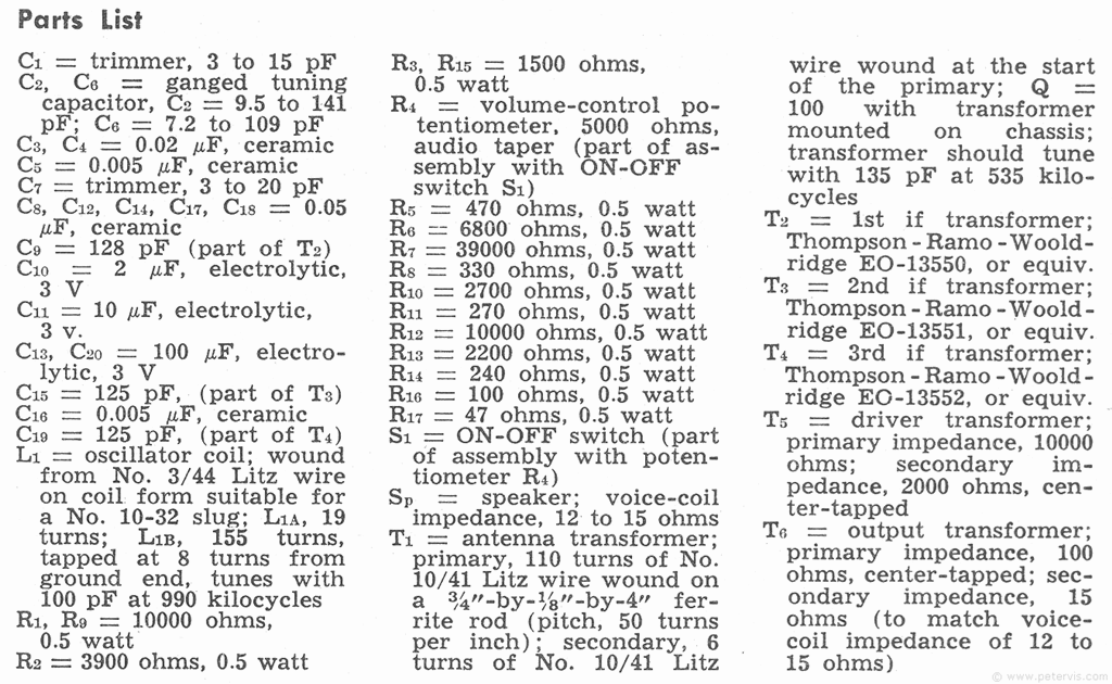
This 3 V superheterodyne radio uses six low-voltage germanium transistors. The converter stage takes the modulated RF signal and mixes it with the local oscillator signal produced by L1B, C6, and C7. The resultant IF signal is 455 kHz (difference frequency). The tuning capacitor for the antenna (C2), and oscillator capacitor C6 are mechanically ganged such that the difference frequency is always 455 kHz. Capacitors C1 and C7 are called trimmers and their purpose is to maintain the required tracking calibration. The inductive coupling between the coils L1A and L1B provides the necessary positive feedback for the oscillator.
The signal passes through two IF stages, where each IF stage consists of 2N1524 transistors. Once amplified it then goes through the second detector, which is basically just a diode (1N295). This diode rectifies the RF signal demodulating it, and capacitor C3 filters out the RF components so that only the audio frequency (modulating signal) remains. This audio signal is developed across the volume control potentiometer R4. The remaining three transistors form a basic push-pull power amplifier, which amplifies the audio signal sufficiently enough to drive a loudspeaker. This type of circuit usually provided 25 mW of audio power output.

Although a circuit such as this would be difficult to make today, as the germanium transistors are not readily available, it lets one appreciate the complexity involved in such pocket radio designs.
This Article Continues...
AM Pocket Radio (Solid State)AM Pocket Radio Electronics
Typical Transistor Radio
Audio Output
Regency TR1-G
3V Germanium Transistor Radio