AM Pocket Radio Electronics

This pocket radio is a five-transistor design. Usually one transistor is for the mixer and local oscillator, and one for the intermediate frequency (IF) amplification. There are usually three transistors for the class B push-pull audio output stage. In this stage, one transistor usually drives a phase splitting transformer, and each phase then feeds its respective power transistor, which in turn, feed their output to a phase combining transformer that then drives the loudspeaker.
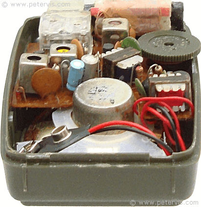
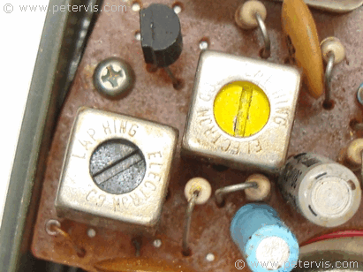
If you have a dead radio that does not make any sound, then check for loudspeaker hiss. If there is a hiss then the amplifier stages are likely operating and you need to focus on the IF section and local oscillator. The transistor for the local oscillator is usually very sensitive to transient spikes and it is possible to knock it out.
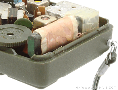
Here is the Ferrite rod and coil.
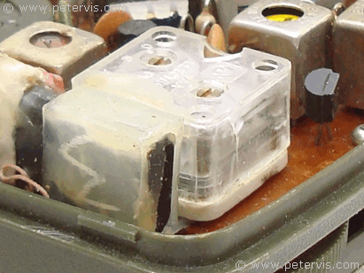
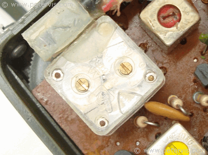
This is the variable tuning capacitor.
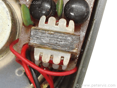
Here is the audio transformer that drives the loudspeaker. The following pages of this article shows vintage pocket radios and their circuits.
This Article Continues...
AM Pocket Radio (Solid State)AM Pocket Radio Electronics
Typical Transistor Radio
Audio Output
Regency TR1-G
3V Germanium Transistor Radio