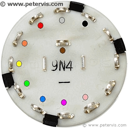
8 Band Crystal Radio Selector Switch Pinout

I managed to get this rotary selector switch for two pounds. It is called 1 Pole 12 Way Rotary Switch. This means that I can select from a maximum of twelve different coil taps if I wanted, however, in this project there are only seven taps.
I might use the other unused switch positions for station presets in the future; hence I have left those unconnected.

When the shaft rotates, the centre terminal makes a connection with all the other terminals on the outside.

The colour-coded dots show the sequence of wiring to the switch. It all starts from the first terminal with a black dot next to it. You solder a black wire there. Then a grey coloured wire to the terminal with a grey dot, and then red wire to the terminal with the red dot...
In the wiring circuit diagram, and the schematic circuit diagram, I have also numbered them as well.

The centre terminal has a brown coloured wire soldered to it. This wire is the selector pole and marked as S in the circuit diagram. This is how it appears after soldering all the wires.
Related Articles
8 Band Crystal Radio (Project Ultra)Circuit Diagram
Stage 1:Making the Coil
Stage 2:Selector Switch Pinout
Stage 3:Installing Selector Switch
Stage 4:Wiring Circuit Diagram
