RFC - Radio Frequency Choke

A Radio Frequency Choke (R.F.C.) is a basic inductor used to choke radio frequencies. This kind of inductor will allow DC current to pass through but block AC current in the radio frequency range. In other words, it chokes the radio frequency signal.
The value of a choke is usually in Henrys, which is an SI unit. The Whippersnapper's Crystal Radio project does not need a choke; however, I am including it for future experimentation.
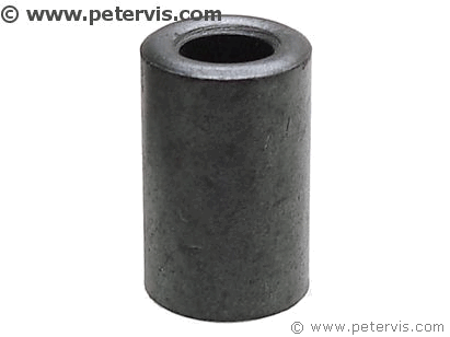
RF Choke

One of the most common problems with using a choke is that its magnetic field often interacts with that of the coil on the ferrite rod. This interaction can cause a feedback loop within the circuit. However, if you mount the choke vertically, whilst the ferrite rod is horizontal, then the interaction is minimized, but sometimes even that will not work if the two are close together.
One of my whippersnappers discovered that if you used a cylindrical shaped ferrite core and wound a coil around it, instead of through it, the interaction is further minimized. Perhaps a Physics Professor out there can tell us why it works so well. I would like the explanation in terms of Maxwell Equations... The cylindrical core is 27 mm high, with an outside diameter of 17 mm, and an inside diameter of 11 mm. You need approximately 25 turns of coil tightly spaced. The coil thickness I am using here is 24 AWG.
The core costs around a pound on eBay, however, look for something cheaper if they have hiked up the prices. My friend Rufus... wound some coil around an iron nail once and it worked for him!
Installing the Choke

To secure the choke, I simply used some hot melt glue from a glue gun, and it was attached robustly. You cannot use screws or any metal near the core, as this will change its electrical characteristics.

Remember to scrape off the insulation at the ends of the coil wires before installing the terminals. I went one further and tinned them so that my whippersnappers would not have any problems when they were experimenting.

This shows exactly where it connects. As you can see, it connects between screw cup terminals 3 and 4 on the lower row.
This Article Continues...
Making a Crystal Radio Electronics LabCrystal Radio Baseboard 4-inch by 12-inch by 1/2-inch
Crystal Radio Baseboard 4 inch by 12 inch by 1/2 inch
No. 6 Brass Screw Cups & No. 6 Screws 1/2-inch
Marking Out the Baseboard and Installing the Screws
Making the coil
Crystal Radio Coil
Crystal Radio Coil Winding
Crystal Radio Coil Terminals
Connecting the Crystal Radio Coil
Main parts
Crystal Radio Diode
Germanium Diode Test
Crystal Radio Earphone
Crystal Radio Circuit
Crystal Radio Specification
Optional
Potentiometer Mounting Bracket
RFC - Radio Frequency Choke
Project Power Supply Wiring
10k Potentiometer Wiring
BC549C Lead Extensions for Future Amplifier Projects
Wiring the Speaker to the LT700 Transformer
Credits
The Little Whippersnapper's Radio
