Crystal Radio and Ferrite Coil Antenna

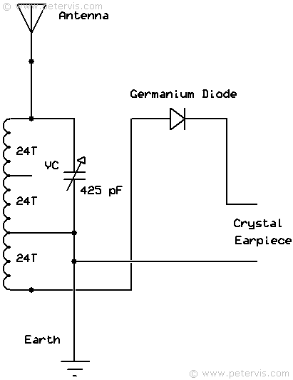
Once you have constructed the ferrite coil antenna, you may test it by installing it in a crystal radio circuit. This may also be an appropriate time to hook up the aerial and ground wires and find a suitable variable capacitor.
Simply connect the ferrite coil as shown in the circuit diagram. For this construction, you will require a crystal earpiece, a variable capacitor, and a germanium diode. The aerial wire is two metres long ceiling high, and the earth wire is 2-metres long dangling from the desk to the floor. If you are using the correct components, then you should hear at least one strong station, and around three to four weaker stations. If you can get at least that much, then your transistor radio will work fine when you construct it. If you cannot hear anything, then you need to focus on this part of the circuit until it is correct.
If you are living in the London SE area, then you should be able to receive Lyca Dilse at 1035 kHz. It is usually a very strong signal, whilst the rest will be much weaker.
This Article Continues...
MK484 RadioFerrite Coil Antenna
Crystal Radio Tuning Capacitor
Crystal Radio and Ferrite Coil Antenna
MK484 Power Supply Design
MK484 Radio Circuit Stage 1
MK484 Radio Circuit Stage 2
MK484 Radio Circuit Stage 3
MK484 Radio Circuit
MK484 Radio Breadboard Layout