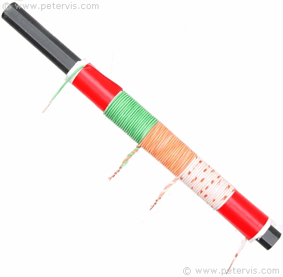
Ferrite Coil Antenna


The ferrite coil antenna is the front end of a radio receiver, which is part of the tuning circuit. It is the most critical part of a radio receiver because it receives the extremely weak radio signals. All radio receivers that receive signals in the medium wave (MW) and short wave (SW) bands require this component, which consists of a rod of high permeability ferrite material and a low resistance coil wire. The coil wire loops around the ferrite rod to produce an inductance. Introducing a capacitance in parallel produces a tuned LC circuit that resonates at a specific frequency determined by the values of inductance (L) and capacitance (C). By varying the capacitance, using a variable capacitor, we can make this combination of components resonate at different frequencies, and thus form an electronic tuner.
The construction of this ferrite coil is simple utilising widely available parts. The ferrite rod is 10 mm in diameter and 16 cm in length, and the actual length of the coil occupies 6.7 cm, hence a ferrite rod of any length greater than that should work.
The coil wire comes from a CAT 5 UTP computer networking cable, which consists of four pairs of solid core twisted wires, which are unshielded. Only one metre is required for this construction, and the first step is to remove the outer insulation to get to the twisted pairs, which require separation and straightening.
The wire loops around a paper former, which is essentially just a paper tube. To make the paper tube, place the ferrite rod on a standard A4 sheet of copier paper (80 gsm), roll the complete length of the paper onto the rod, and secure the end with some tape.

This project requires only three wires for the coil construction. Take the first wire and leave an inch for the terminals. Secure the end with some tape and then wind the remaining wire leaving only an inch at the end to make a tap. Take the second wire and join it to the previous one, and continue winding in the same direction. Repeat for the final wire and secure its end with some tape. Wind the wires in the same direction so that you have a coil with three sections and two taps as shown in the photograph.
I tried many different coil wires, but in the end, this wire appeared to produce the strongest signal, and an advantage of it is that it is cheap and readily available. Almost anyone working in IT will have some, and you can always find it at hardware stores, and online shops, including your local Maplin. The average cost is approximately 40-pence per metre, and you need only one metre.
This wire tends to work well because the copper they use is usually high-grade low resistance type, which helps to improve the selectivity.
This Article Continues...
MK484 RadioFerrite Coil Antenna
Crystal Radio Tuning Capacitor
Crystal Radio and Ferrite Coil Antenna
MK484 Power Supply Design
MK484 Radio Circuit Stage 1
MK484 Radio Circuit Stage 2
MK484 Radio Circuit Stage 3
MK484 Radio Circuit
MK484 Radio Breadboard Layout