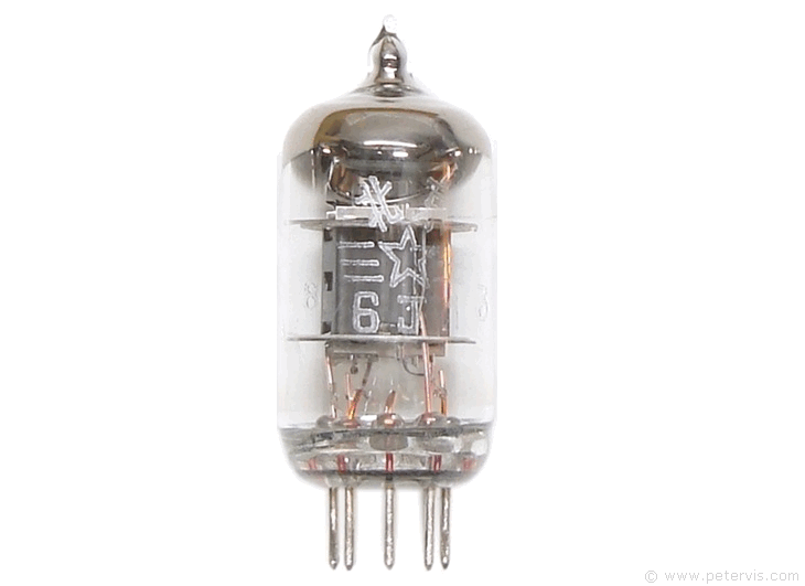
6j1p

The 6j1p is a high frequency pentode valve manufactured by the Voskhod factory in Russia. It is a seven-pin electronic component requiring a B7G base socket for connection, and 6.3 V for the heater filament. Using a 6j1p pentode as a triode is a very simple task, but unfortunately very few people understand how a pentode operates, however you might be wondering why use pentodes at all in the first place. Triodes are getting expensive due to their ever-dwindling stocks, and looking on eBay, the cost of a ECC81, ECC82, ECC83, and ECC85 has sky rocketed. However just recently I came across a cheap valve 6j1p selling for just one pound. It is very similar to the Russian 6z1p pentode and I was intrigued because there must be a factory out there making them! Pentodes were widely used in television sets and there is plenty of old stock floating around because nobody knows what to do with them. Pentodes can have many advantages over triodes if used correctly, and this page explains how to use such a component.
Pinout and Operation

British scientists did much of the pioneering work for the development of the pentode. Engineers usually prefer pentodes because they have the ability to direct the electron beam specifically to increase the power handling capability and simultaneously input sensitivity. Such tubes have advantages of high power output, high input sensitivity, and high efficiency. They were heavily used during the Second World War, and many would consider pentodes such as the EF50 playing an instrumental role during that time. A pentode usually consists of an anode (often referred to as plate A), and a heated cathode (K). It also has grid number one, also called the control grid, grid number two (screen grid), and grid number three (suppressor grid). Each of these grids have a specific purpose in directing the electron beam.
When electrons from the cathode strike the anode plate, they usually dislodge other electrons. Emissions caused by this type of bombardment are secondary emissions and undesirable. To reduce the effects of secondary emission, grid number three, the suppressor grid, is usually used. It connects directly to the cathode and has a negative potential. This negative potential causes the electrons to repel from the suppressor grid thereby pushing them back towards the anode plate. In the 6j1p, the manufacturer has pre-connected the suppressor grid to the cathode internally. Therefore, expect pins 2 and 7 to be common when testing for continuity with a meter.
Secondary emissions became very important in the development of the valve, because since one electron dislodges multiple electrons from the anode plate and the suppressor then pushes these back to the anode again, then these multiple electrons striking the anode plate result in a degree of amplification. Valves later developed such as the EE50 especially to make use of this secondary emission. My thoughts about this were that it is quite possible that valves that make use of the secondary emissions will operate well at lower voltages for my radio circuits.
The function of the screen grid (grid number two) is somewhat different. The Miller Effect is an increase in the input capacitance due to the grid-to-anode capacitance reflecting back to the grid thereby affecting the frequency response of the input. To prevent this from happening, engineers employ the screen grid (grid number two) to provide a shield between the anode and the control grid (grid number one) thereby reducing this capacitance. Doing so, results in making the input extremely sensitive to high frequency signals.

Theoretically, if we ground the screen grid, then it behaves as a "Faraday" or electrostatic shield resulting in the reduction of control-grid-to-plate capacitance. This capacitance drops to a low value making the control grid very sensitive, and this is desirable. Consequently, screen grid tubes are much easier to drive than triodes because they require lower signal at the control grid. However, making the grid negative would make it repel the electrons and that is undesirable. Therefore, in practice, we do not connect the screen grid directly to ground, but instead connect it to ground through a bypass capacitor Cacg. Hence, the screen grid effectively connects to an AC ground. However, we do connect it directly through resistor RG2 to a positive DC voltage source in order to accelerate electrons towards it.
This Article Continues...
One Valve Radio6j1p
One Valve Radio Circuit
One Valve Radio Construction
One Valve Radio Regeneration Coil
One Valve Radio Power Supply
Ferrite Rod Antenna Coil