One Valve Radio Circuit

This low-voltage one valve radio circuit uses the 6j1p pentode to operate as a triode. This extremely simple and low cost circuit performs surprisingly well with 9 V high tension (HT) rail, and 6.0 V heater. In valve/tube nomenclature HT is simply a term that describes the supply voltage between the anode and the cathode. Usually, it is a high voltage that produces sufficient electron flow between the anode and cathode plates, however, in this circuit we are using only 9 V. In this radio circuit design, I am also connecting the screen grid directly to the anode plate. Making the screen highly positive has the effect of causing electrons to accelerate towards it, which may be advantageous when operating a valve in starved conditions. However obviously in these low-voltage conditions, we are in unchartered territories. We need the control grid input to be extremely sensitive and for that reason, I am using a 10.5 MΩ resistance in parallel with 1000 pF capacitor. I believe, this will take the valve pretty much to its amplification limits. During the design phase, I noticed that increasing the value of this capacitor and placing a very large resistor in parallel with it was having the effect of increasing the gain. (The sound was getting louder!) Hence, I kept increasing it until I reached these values. Much later, my friend Cliff told me it was due to a phenomena known as grid-leak.
Since the 6j1p is to operate in starved conditions from a safe and low 9 V, there is no cathode resistor, and therefore pin 2 and pin 7 connect directly to the ground rail. For the anode plate, 100 kΩ resistor appears to be appropriate for 9 V operation. This is a very critical component value because if you change the voltage, then you will need to change the value of this resistor. Therefore, in order to fix this characteristic, I am using a 9.0 V voltage regulator (7809), so that the DC anode voltage remains constant no matter the power supply used by the hobbyist.Using a voltage regulator IC for the anode voltage is something I have never seen before, but it does seem to work well.
Imagine the negative electrons shooting from the cathode like bullets, and the screen causes them to accelerate towards it even more due to its strong positive potential. Some electrons will shoot through the screen and approach the suppressor, which is negative. The suppressor will push some of the electrons back to the screen if they do not have sufficient kinetic energy to continue. However, some electrons will have sufficient kinetic energy to shoot past the suppressor, and they will hit the anode plate. If they bounce back off the anode plate, and not have sufficient kenitic energy, then the suppressor will push them back to the anode.
Screen Grid Capacitor Experiment

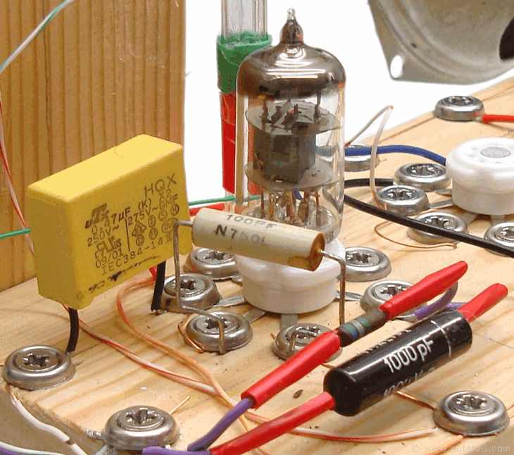
If your one valve radio circuit works well this far, then you might recall that in the 6j1p article, I mentioned the use of a capacitor between the screen grid (pin 6) and ground. This capacitor provides an AC ground and is vital. To understand its importance, if you tune into the weakest, but clear, radio station, and connect a 100 pF capacitor between pin 6 and ground, then you should notice the sound increases in amplification by approximately two fold. This configuration also removes the RF from the anode line, which is standard practice.

If you permanently secure it between pin 6 and pin 7 screw cups, and then retune, you should notice all the stations being louder! Part of the reason why that happens is because providing the screen with an AC ground through the 100 pF capacitor makes the control grid (pin 1) more sensitive to the RF signal.
This Article Continues...
One Valve Radio6j1p
One Valve Radio Circuit
One Valve Radio Construction
One Valve Radio Regeneration Coil
One Valve Radio Power Supply
Ferrite Rod Antenna Coil