TA7642 Ferrite Coil Connection

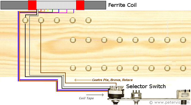
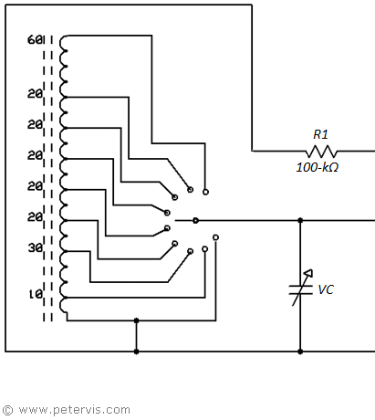
The most critical aspect of this radio build is the ferrite coil and variable tuning capacitor. If you can build the coil very accurately, with the correct radio coil, and get a high quality tuning capacitor, then this build has a good chance of working. The first stage is to build the radio coil as shown in Project Ultra, which is the 8 Band Crystal Radio (Project Ultra). If you can get a couple of stations on some of the band settings, then that will work very well with the Radio IC. As you can see from the circuit diagram above, the taps on the ferrite coil connect to different coloured wires. These wires solder directly to the selector switch. The "selected" return wire from the switch is brown coloured. One end of the coil connects to earth, and it connects to the rotary switch as the first selection. In this position, there is effectively no coil in the circuit, which is very useful for experimental purposes.

Here is the circuit diagram of the ferrite coil section.

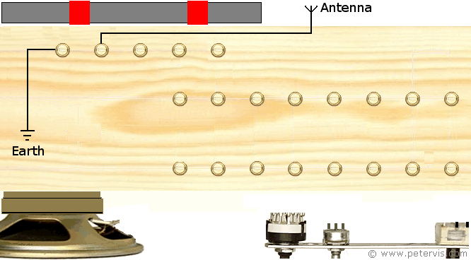
When I first switched the radio ON, I heard some faint whistling and radio signals, but nothing significant. Then I realised that in the excitement, I had forgotten to connect the earth and antenna wires! I had a long piece of wire on the floor connected to the radiator pipe, and as soon as I connected it, I started receiving some strong signals. The antenna was just a short 2-m wire to the ceiling; however, I later replaced it with a telescopic aerial from a thrift store. They had one of those cheap ones for televisions, with a pair of whip aerials. It was ideal for my use because it extended to 1-m.
This Article Continues...
TA7642 AM Radio - Project TomTA7642 AM Radio Baseboard Construction
Ferrite Coil
TA7642 Ferrite Coil Connection
Radio Stage
TA7642 AM Radio IC
TA7642 Power Resistor Rp
TA7642 Circuit Build
Amplifier Stage
LM386 Amplifier - TA7642 AM Radio
LM386 Circuit Build
Misc
TA7642 Circuit
TA7642 AM Radio Parts List
TA7642 AM Radio Parting Shots