Three Transistor Radio - Whippersnapper 3 Build Stage 1
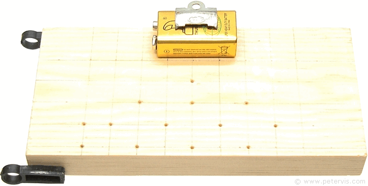
The build is on a nice piece of pinewood measuring 18 cm × 9 cm × 2 cm, and we are using the no.6 screw-cup system consisting of countersunk half-inch wood screws. The first stage was to measure out a 15 mm square grid pattern for the alignment of the transistors.
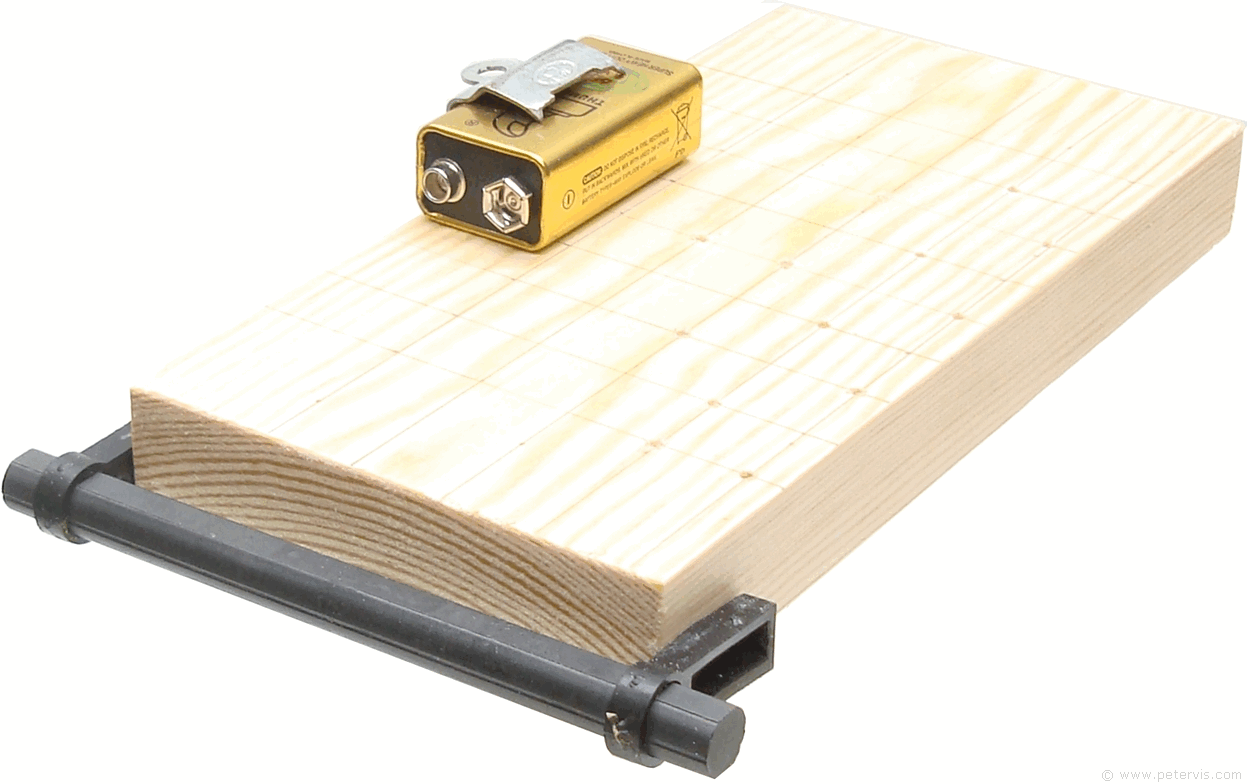
You then need to determine the positioning of the main components such as the variable capacitor, power switch, headphone socket, and telescopic antenna, and finally secure them to the board using some clear hot melt glue from a glue gun.
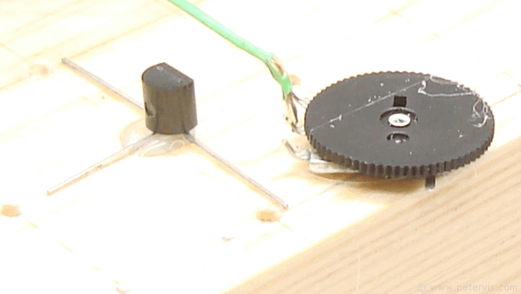
In order to minimize crosstalk, it is good practice to keep all the wires as short as possible, therefore this is a precision and compact build. For the volume control, I am using some rotary types that are very affordable (ten of a pound). This time the circuit dictates the positioning of the volume control, and I decided to fit it there instead of somewhere more convenient, that would require wire extensions. Luckily, it ended up in a good place that is away from the ferrite coil and aerial. Again, I used a small blob of clear hot melt glue to secure it in place, just near the edge.
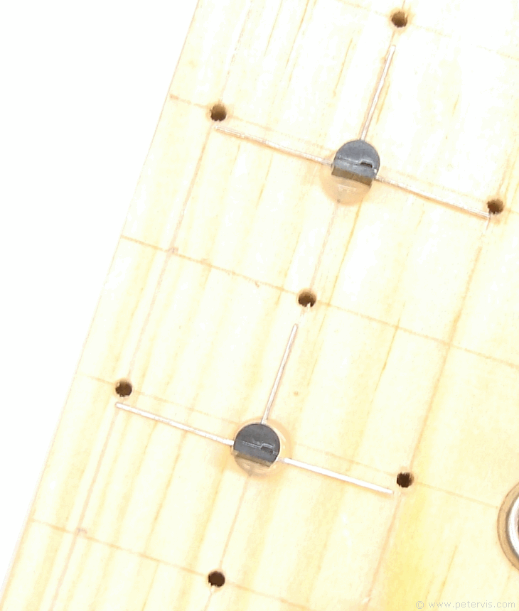
In this build, I spread out the terminals of the MPSA13 transistor as shown to increase the space between them for using the screw-cup system. I also applied a blob of clear hot melt glue from a glue gun to secure them so that they do not move when I unscrew any one of its terminals.
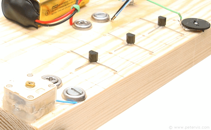
When they spread out in this way, the terminals are 15 mm in length, hence I decided to align their terminals on a 15 mm grid pattern, which keeps all the transistors close and minimizes the number of screw-cups used.
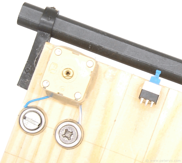
Before you secure the variable capacitor with glue, you will need to do some wiring to it. If you are using cheap 224 pF ones marked "FU" at the front, then you will need to know how to wire it. I have a special article PVC-224 Variable Capacitor, which shows how to wire it. The power switch is optional but can be useful, otherwise you will have to remove the battery terminal wires when switching OFF. It is single pole locking type, and ideally it has to be plastic and small because of its proximity near the ferrite rod.
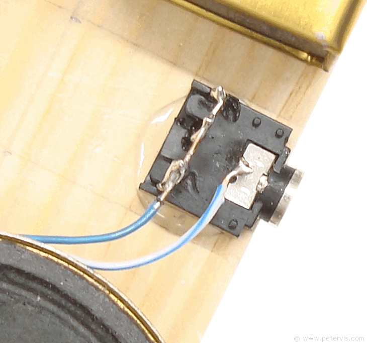
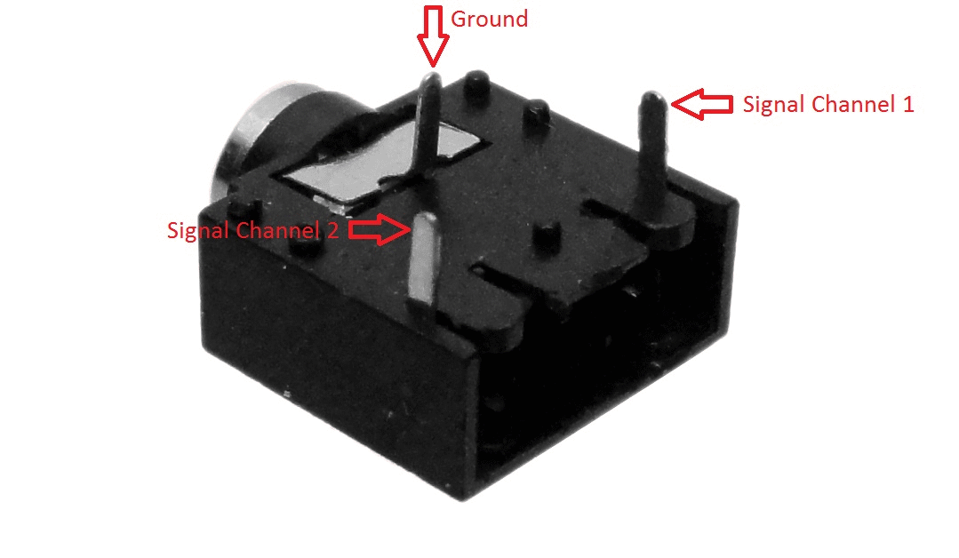
I decided to connect a temporary headphone socket (quick fashion) just to hear how it sounds through a pair of headphones. I am using one that I happened to have, which is usually used in Walkman-style stereo cassette players. They are very simple with just three terminals (signal channel 1, signal channel 2, and ground). I have simply connected the pins of the two signal channels together using a long piece of wire so that I can hear the sound on both sides of the stereo headphones.
Many headphone sockets have built-in switches that will disconnect the loudspeaker when you insert the jack plug and they are the most ideal to have. They can come in a variety of designs and pinouts, and if you are using a recycled part then the best way to determine the pin collections is to use a multimeter in continuity mode.
This Article Continues...
Three Transistor Radio - Whippersnapper 3Circuit
Build Stage 1
Build Stage 2
MW Antenna Coil
TDA2822 Bridge Power Amplifier