Three Transistor Radio - Whippersnapper 3

This three transistor radio "The Super-dooper" is part of my Whippersnapper series of radios I have been developing on the screw-cup system. This radio is similar to my first three transistor radio in that it uses the MPSA13 Darlington transistor to amplify the radio frequency (RF), however this time, for driving the loudspeaker, I am using my newly developed power amplifier that is ear splitting loud. It uses the TDA2822 dual power amplifier IC configured in a bridge circuit and capable of providing 1.35-watts into a 4 Ω loudspeaker at 6 V power supply. In this radio circuit, I am using a PP3 9 V battery for the power source, and an 8 Ω loudspeaker, which produced very loud and clear audio.
The TDA2822 IC and MPSA13 are readily and cheaply available online, and they have many advantages over other components I have used before. Firstly, the IC requires very few external components; secondly, it is possible to configure it into a bridge-tied-load (BTL) output to drive a 1-watt speaker in low-voltage battery powered applications making it very efficient. The MPSA13 is a Darlington transistor, which I discovered many years ago in the Whippersnapper article to amplify RF. The three transistors provide the brute force for amplifying the raw radio signal. They amplify it to a point that if you were to connect a normal pair of headphones, you can very faintly hear the audio, and that is all we really need because after that, it goes to the power amplifier to drive the loudspeaker.
I have designed it like this to keep the component count and price as low as possible, consequently everything should be available on eBay. I have also tried to make it as simple as possible to build it using the number 6 screw cup system. This is a very realistic design that any hobbyist could build, and it works well. In fact, this will probably be your first radio that works well compared to all the designs you tried in those expensive magazines.
Power Amplifier Module

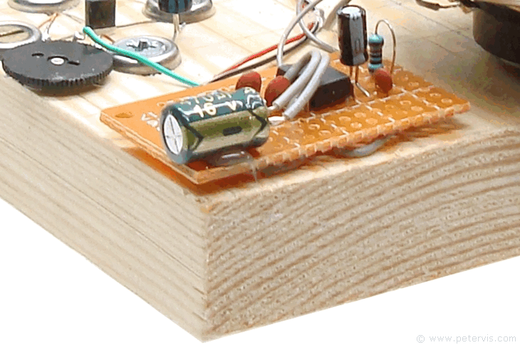
Back when I first designed the 3-transistor radio circuit, I ended up using the LT700 step-up transformer, which works very well, however many people around the world were asking if there was a cheaper alternative as they were unable to source this component. The only other option was to use the LM386 IC, however this IC has a fixed internal gain that does not react well to fast RF signals. They just pass through without much amplification, and increasing the gain only ends up creating squeaks and squawk sounds caused by feedback and crosstalk. The second option was to try the TDA7052, however it too has a fixed internal voltage gain (of 40 dB), however it performs slightly better than the LM386, but it is not very loud. What I needed was a cheap power amplifier IC, capable of keeping up with the fast signals. All I wanted it to do was to provide the necessary current gain to drive the loudspeaker, however it is easier said than done! I then went back to the drawing board, trawled through IC specs, and discovered the TDA2822. It requires only eight additional components to work, and more importantly, it is able to keep up with the fast RF signal! Therefore, I suspect that this IC and amplification circuit will become something special to all radio engineers, when they discover it on this site and make it for themselves. Currently, there are no ready-made modules available, however it is possible to build it on a small piece of strip board as shown here, and it works extremely well. You will be very pleased!
The Tank Circuit

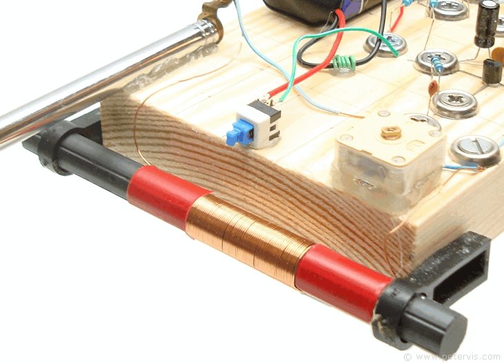
The tank part of the circuit consists of the ferrite rod coil and variable capacitor connected in parallel. When a coil and capacitor are connected in parallel, they produce resonance at a frequency determined by the inductance of the coil, and capacitance of the variable capacitor. As you can imagine, when you change the capacitance (through the variable capacitor), the resonant frequency changes accordingly. Hence an arrangement such as this can produce a series of different resonant frequencies as one turns the variable capacitor. When the resonant frequency is equal to the frequency of any particular radio station carrier wave, the tank circuit is said to be tuned for the reception of that station.
A good reason for giving this three transistor radio another go was that this time, the tank circuit is more standardised using a cheaply available variable capacitor, ferrite rod, and CAT5e wire. I tested this combination of components on high-end spectrograph equipment and it performed very well. I wanted something that was as low-cost as possible and worked well, and therefore I use it for most of my projects, until something cheaper comes along... You can of course use your own tank arrangement, however as Scotty always says, I cannot guarantee it!
When I first built the radio, the only wires I had left from the CAT5e bundle were the white ones of the pair, and it does not photograph well (but it does work well). Therefore, for photographic effect, I found another lovely shiny golden looking coil that is the same thickness as the CAT5e wire, and amazingly still required 70 turns on a 10 mm diameter ferrite rod.
You can see the circuit and the build in the following pages of this multi-page article.
This Article Continues...
Three Transistor Radio - Whippersnapper 3Circuit
Build Stage 1
Build Stage 2
MW Antenna Coil
TDA2822 Bridge Power Amplifier