High Gain Darlington Pair – Circuit

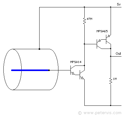
High gain amplification is feasible through a Darlington configuration, invented by the Bell Laboratory engineer Sidney Darlington in 1953. In such a configuration, the total DC current gain of the circuit is the product of the individual gains of both transistors as shown by the following formula.
hFE = hFE1 × hFE2
In this formula, the individual gain values of the transistors are hFE1 and hFE2. Therefore, I decided to use a MPSA14 transistor, which has an hFE current gain of 20000.
Circuit Simulation

The circuit above shows a spice simulation where a small current of 1-pico-amp is injected to the base of Q1, causing and output voltage of 0.02 V to be detected. The circuit can therefore detect a flow of current in the ionisation chamber as low as 0.5-pico-amps providing an output of 0.01-volts, which is easily within the resolution of the microcontrollers ADC range.
High Value Resistors
If R2 is doubled to 94 MΩ, and R1 is set to 94 MΩ the output voltage is much higher and becomes 1.89-volts for a 1-pico-amp input. The sensitivity then shifts to the femto range, where 10-femto-amps produce an output of 0.04-volts. Hence, increasing the values of both R1 and R2 as much as possible increases sensitivity a great deal, and the problem simply becomes one of sourcing high value resistors.
High value surface-mount resistors have been available for a long time. They are available in a 0805 IRC type package, with values ranging from 100 MΩ to 50 GΩ. The 1085 package is 2 mm × 1.25 mm in size, and small enough to fit onto a very small circuit!
On the simulator, 100 MΩ for both R1 and R2 produced an output of 0.53 V, when the input was just 10-femto-amps.
Circuit Characteristics Graph

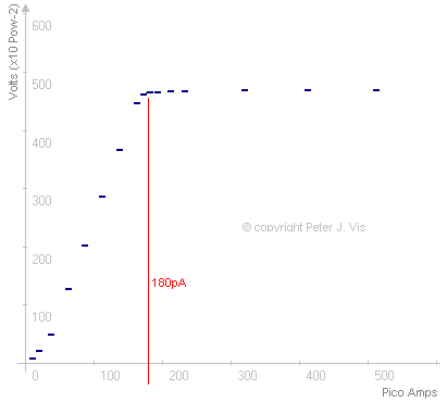
In this graph, R1 = 47 MΩ, and R2 = 1 MΩ. This is a response graph of input current in pico amps versus output in volts shows. The Darlington pair reaches saturation at around 180-pico-amps producing an output of 4.95-volts. The output then rises very slowly to 4.99-volts at 500-pico-amps.
This Article Continues...
007 Gadgets: Polonium DetectorPolonium - Po
Ionisation Chamber
High Gain Darlington Pair – Circuit
ATtiny Microcontroller for Processing
1.5 V to 5 V Converter Power Supply Chip
Polonium Detector Conceptual Design
Polonium Detector Schematics