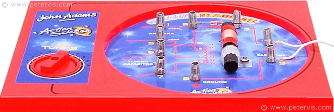
John Adams Crystal Radio Kit Ferrite Coil Wiring
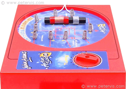
The photograph on the box shows the ferrite bar installation upside-down, and all the antenna coil wires fed through a single hole. Do not follow that, as it is wrong. Instead, follow the diagram on page 4 of the manual, or this page.
Connections
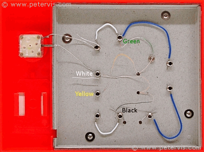

- Black wire to Terminal 2
- Yellow Wire to Terminal 5
- White Wire to Terminal 6
- Green Wire to Terminal 8
Ferrite Rod and Coil
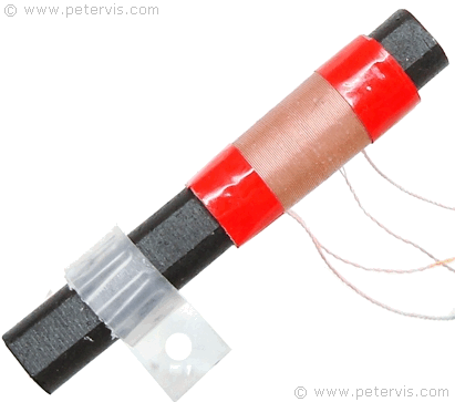
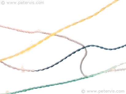
Antenna Coil Colouring
Wire Routing
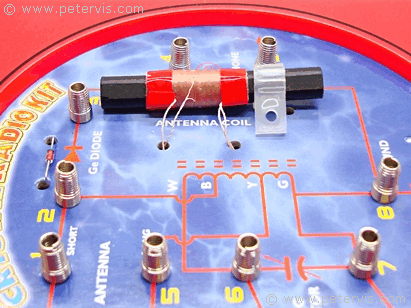
The green and yellow wires from the antenna coil feed through the RHS hole, whilst the black and white wires feed through the LHS hole as shown in the photograph. The remaining hole is for securing the ferrite bar using a nut and bolt. Slide the coil to the far edge of the ferrite rod so that only 5 mm of the rod is showing from that end.
Securing the Rod
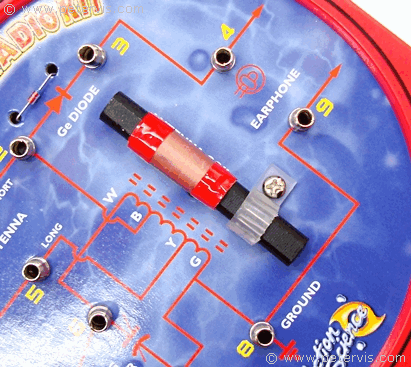
After routing the ferrite coil wires through the relevant holes, use the remaining hole for securing the ferrite bar using the supplied nut and bolt.
This Article Continues...
Crystal Radio Kit John AdamsJohn Adams Crystal Radio Kit Diode
John Adams Crystal Radio Kit Crystal Earpiece
John Adams Crystal Radio Kit Variable Capacitor
John Adams Crystal Radio Kit Ferrite Coil Wiring
John Adams Crystal Radio Kit Parts
John Adams Crystal Radio Kit Box
