Ceramic Cartridge Preamp Circuit -- Pete's MOSFET Preamp

This ceramic cartridge preamplifier circuit requires the least number of components and produces a decent sound with minimal loss of bass and treble inherent with such cartridges. It uses the 2N7000 MOSFET transistor, with minimal biasing overhead. Ceramic cartridges of capacitance range 800 pF to 12,000 pF, and absolute maximum voltage of up to 900 mV could theoretically be used; however I have tested it only with that cheap Universal Ceramic Cartridge and Stylus available on eBay. Hence, please only use this circuit with that cartridge as I do not know how it will perform with all the different modern and vintage, types, and makes of ceramic cartridges out there. Many of them such as crystal cartridges can have extremely high output voltages that are outside the input voltage range of this circuit, and therefore they will not work. My design concept was to produce a circuit that would provide the best possible sound, using the most commonly available and lowest-cost components. I tested it with readily available general purpose NPN transistors and they worked up to a point, however, there was a limitation to the absolute maximum input voltage the base junction could accept before distortion occurred. Some of the transistors that I tried were the MPSA13 Darlington, 2N3904, and 2N2222; however the 2N7000 MOSFET produced the best sound out of all.
The secret to the circuit is that I am using an equalization network that provides feedback to the gate junction, which has the effect of lowering the input impedance. Simultaneously, I am using a MOSFET that has very high gate impedance, which eliminates cartridge loading issues almost entirely, and consequently the sound quality is excellent to say the least. Audiophiles should love this circuit as it is minimal, and easy to build on stripboard.
When we use general-purpose small-signal transistors, we usually end up having to include a base junction resistor to reduce the high voltage of the ceramic cartridge. Since any resistance at the base junction has the effect of reducing the treble (because the cartridge is purely capacitive resulting in an RC-type filter being produced) it occurred to me to try other transistors that allow for a higher base junction input voltage, and thus eliminate the need to use a resistor.
For decades there were myths that an input resistor increases bass, whereas in fact it actually cuts treble resulting in dull low-fi sound. In the B. J. C. Burrows paper of July 1971 (Wireless World), he too mentions the same effect, and of course he was totally correct! Back then, Burrows did not have the wide range of transistors that we enjoy today, and consequently his circuit is very large utilising the BC109 transistors. Due to the input limitation of the transistor he had absolutely no choice but to add an 18 kΩ resistor at the input and a further series variable resistor of value 50 kΩ that he calls Tone Balance.
Electronics is very much like chess, in that, if that first move is wrong, then you end up compensating for it throughout the game. All your efforts in clearing that first error, results in you creating new fresh ones! Hence, shortly after finishing my first ceramic cartridge equalization circuit, I was thinking about how I could feed up to 500 mV into the base junction of a transistor without a base resistor and without any clipping occurring. My first thought was to use the cheap and commonly available MPSA13 which is a Darlington package that I have been using in radio projects. With this transistor I could feed up to 566 mV at its base junction, before any signs of distortions show on the scope. It then occurred to me to try a MOSFET transistor as it has even greater base impedance, so I connected my favourite (cheap and cheerful) 2N7000, and found that I could feed up to 910 mV before any signs of distortions began to show. I then switched my scope view to the frequency response curves and found that the MOSFET had an extremely favourable response. With the circuit built on solderless breadboard and connected to my hi-fi, I decided to see which transistors sounded better and found that the MOSFET produced significantly better sound. Hence this circuit is the MOSFET input approach to RIAA equalization.
Compatible Transistors

| Transistor | Maximum Input Voltage |
| 2N7000 | 910 mV |
| MPSA13 | 566 mV |
| 2N2222 | 292 mV |
| 2N3904 | 267 mV |
With 1 kHz sine wave fed to the base junction of the transistor, and no base resistor, we can find the maximum voltage that we can feed at the junction before the slightest signs of sine wave distortions begin to show. In the case of the MOSFET transistor, obviously it is the gate junction we feed the signal to.
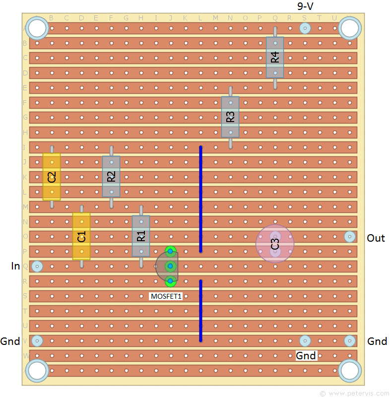
Circuit Layout on Stripboard

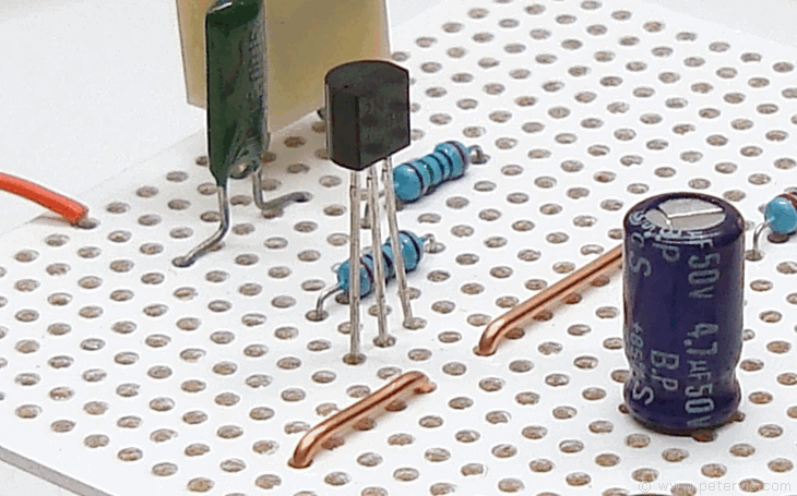
The layout and construction is very simple and there are no cuts required anywhere on the stripboard. There are only two links that basically make the board layout neater and presentable. Notice how the polystyrene capacitor terminals are bent. Do not spread out the terminals in a way that might stress the seal with the main body.

Install the transistor last and minimize the heat to it when soldering by using a heat-shunt. When you handle this MOSFET transistor, be sure to take electro-static discharge (ESD) precautions, because the gate junction is very sensitive. It is possible to have a transistor with a partially damaged gate junction, and it will not provide much gain. Sometimes the gate junction can be damaged completely in which case it will not work at all.
For the power supply, start with a PP3 9 V battery during the construction and testing. Once, you are happy with it, try building this 9-V power supply circuit, which is hum free and works well with the preamplifier. I also finally installed all the circuits into a permanent case.
Parts List
| Part Number | Value | Additional |
| R1 | 20 MΩ | ¼-watt, 1 % |
| R2 | 20 MΩ | ¼-watt, 1 % |
| R3 | 2.2 kΩ | ¼-watt, 5 % or better |
| R4 | 1 kΩ | ¼-watt, 5 % or better |
| C1 | 1500 pF (±10 %) | 100 V, Mylar |
| C2 | 1200 pF (±2 %) | 250 V, Polystyrene |
| C3 | 4.7 µF | (Non-Polarised Electrolytic) 50 V or 25 V |
Cost/eBay

In this build, I am using the cheapest and most readily available components found on Google. The MOSFET transistors usually come in an anti-static bag and I managed to get a quantity of these for a few pounds on eBay. For the electrolytic capacitor I am using a non-polarized type for audiophile quality, however if you cannot find one, then a polarized type will work too.
This Article Continues...
Ceramic Cartridge Preamp CircuitPreamp Equalization Network
