Quadraphonic Decoder Board Completed Build
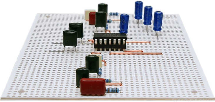
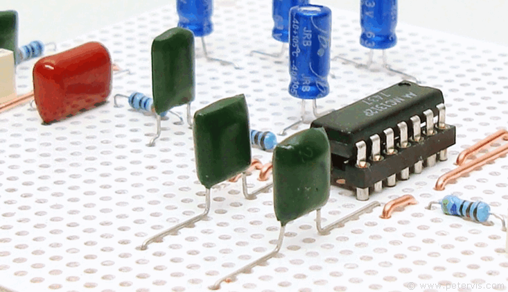
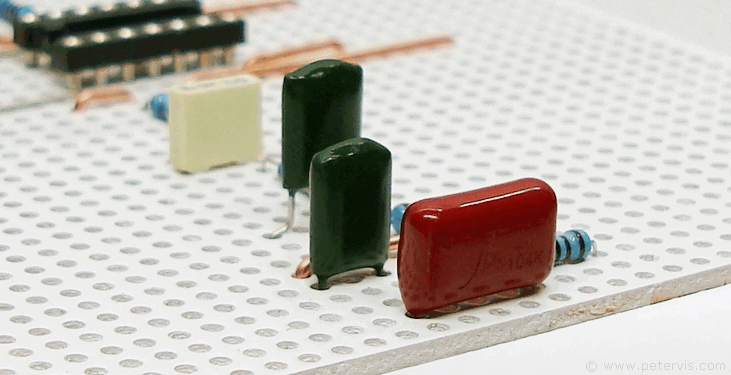
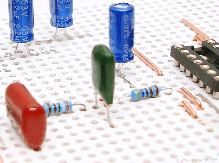
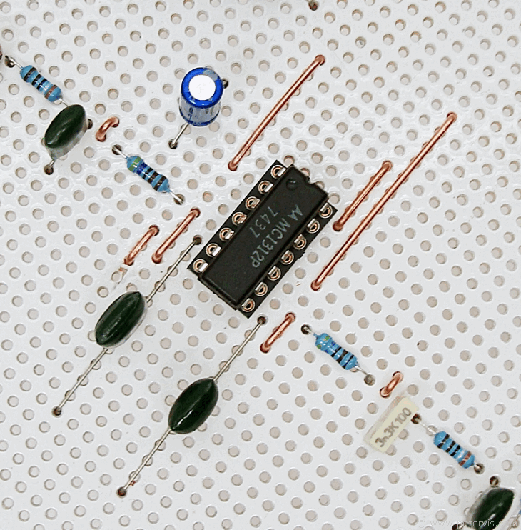
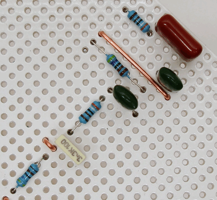
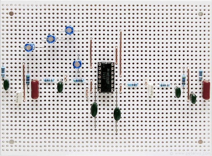
Here are some photographs of the completed build of the quadraphonic decoder board. As usual, I had no problems building this. I first designed the schematic layout, and then the board layout, then ordered the components and installed them in as shown. I flicked ON the power switch and it all worked the first time round without any problems. If you build it carefully, and pay attention to detail then there should be no problems.
This decoder board provides four analogue outputs, two for the front speakers and two for the back, and therefore this stage can be tested by feeding a signal at the input and connecting the outputs to a power amplifier. I did exactly this and was able to hear sound from all four channels when playing non-quadraphonic records. There was a slight discernable difference between the channels as well, which was interesting to hear. The success of this first stage made me realise that it was a good idea to proceed further to building the rest of the circuit. The rest of the circuit builds can be seen on this site in part works, where part 2 and part 3 are for the logic and gain control circuitry. There is also a final part to build a 20 V power supply.

This Article Continues...
Quadraphonic SQ Decoder -- Part 1Completed Build
Installing Links
Components
Soldering
