Quadraphonic SQ Decoder -- Part 1
The MC1312P, MC1314P, and MC1315P are integrated circuits that provide a complete chipset solution for decoding quadraphonic records encoded on the SQ system developed by the Columbia Broadcasting System (CBS). The decoder takes a pair of composite signals (stereo) and separates them out into four channels. Hence quadraphonic records with the SQ logo can play in stereo as normal records, however if one had the decoder, then the stereo signals can be separated into four channels. The decoding is performed by the MCP1312P, whilst the MCP1315P enhances the back to front separation by to 12 dB. This type of enhancement is highly desirable and sounds far better than systems that do not have it. The MC1314P is the gain control block containing voltage controlled amplifiers, which enables volume and balance settings of the channels. This IC reduces the component count drastically and enables the use of low-value single-track potentiometers, instead of high-value ganged ones that are usually expensive.
A quadraphonic recording on vinyl records is something most people may not have heard of. The idea of recording just stereo on a groove is amazing, but then to have four channels, is even more amazing. However, it is possible to buy records that have quadraphonic channels, and these records have the SQ logo on them. If you look at places like eBay and search for Quadraphonic SQ, then there is usually a small selection of records to choose from. Suffice it to say that most of the popular records such as the John Lennon one will be expensive.
In order to listen to these records in four channels, one requires a special decoder that converts the two (stereo) channels into four channels. Back in its time when this system was popular, there were also amplifier receivers that had built-in decoders, however as you can imagine, these are not manufactured anymore and consequently what is available is very expensive to purchase. I was fascinated to learn that it was possible to have four channels on an LP and wanted to get hold of a decoder to experience what it sounded like. Vintage amplifiers that have this decoding facility are usually expensive, which leaves the possibility of making a circuit. However most of the discrete transistor circuits tend to be huge and elaborate, so that was out of the question.
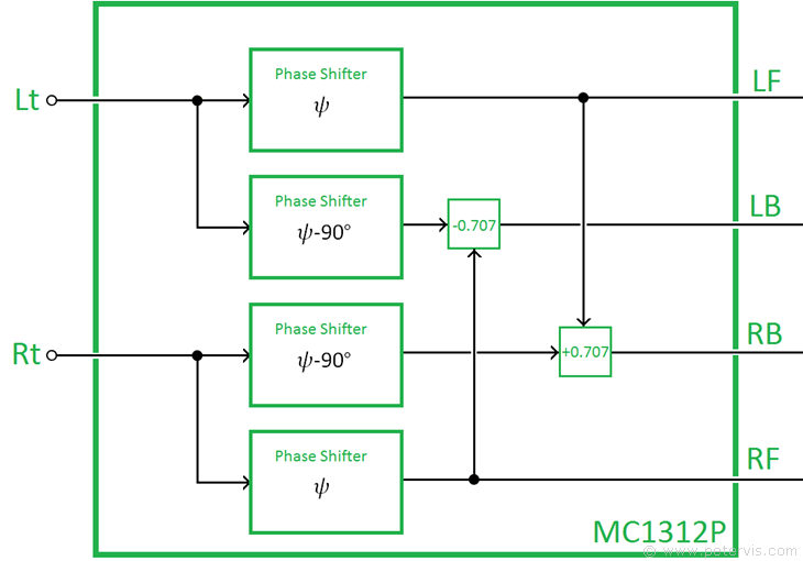
Internally, the MC1312P consists of all-pass networks that produce a phase shift without amplitude variation. These networks are of the Wein bridge type, and their high-precision resistance arms are within the IC package. The circuitry is able to produce 90° phase shift between 100 Hz to 10 kHz, and phase ripple is only ±8.5°. Consequently, in this build, it is advantageous to get high-quality and precision components for a good result.
Luckily, I stumbled upon a Motorola MC1312P IC, which is a four channel SQ decoder chip that reduces the component count drastically. This IC seems to be available and affordable so I figured it would make a good project for my hi-fi. Looking at the documentation of this IC, I noticed that it operated with two more support chips, where the MC1314P IC provides the gain control for the channels, and the MC1315P provides the logic control to improve the separation between the back speakers and front speakers. The logic control essentially switched ON or OFF the relevant pairs of speakers to produce better separation.
At first, my intention was to build just the MC1312P matrix decoder circuit, and feed its output to my amplifier. My amplifier has component 4-channel audio input sockets, with balance and volume controls so I did not need the gain control circuitry. I also did not need the logic control circuitry for additional separation, hence I figured just a small decoder costing less than ten pounds would be enough to quench my curiosity. However as I started designing the layout, it occurred to me that if I planned it properly, I could add the other circuitry later on if I needed; hence it turned into a three-part project.
Of course, it is possible to build the whole circuit with the three chips on a single board, with a crow’s nest of wiring, but then it would not be something anyone could follow, hence I decided to separate it out into three small boards. There is plenty of space on the boards which makes the build simple and gives the constructor the opportunity to add more circuitry if they so wished. In my case, I just wanted a layout with more order so it was easier to build.
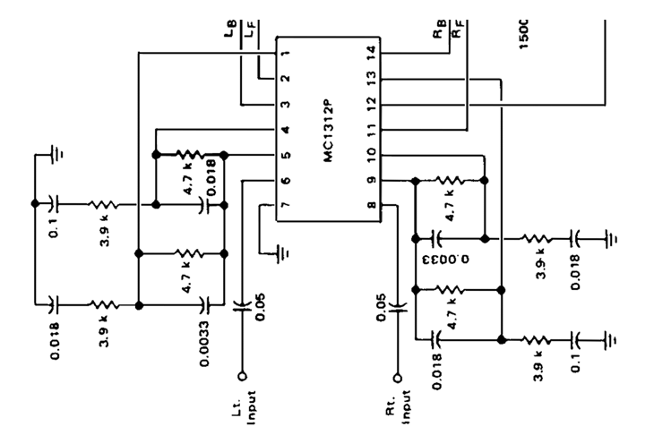
Looking at the original schematic diagram, the first problem I noticed was that the layout was not ideal for a strip-board build, or any sort of build for that matter. Usually, one requires horizontal lines with components connecting to that, because that is easier to translate to a strip-board layout, however the circuit for the MC1312P had vertical connections from pins 5 and 9, and therefore I had to redraw the complete diagram to that shown at the top of this page. Once I had that diagram, it was easier to make the board layout on strip-board.
Component Layout
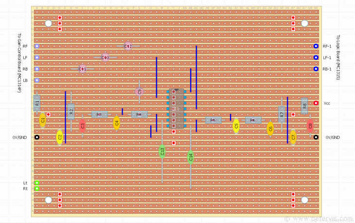

In order to make the build easier to follow, I felt it was important to separate each IC and its circuitry on separate boards. The advantage is that many people may just want to build the matrix decoder part, and not want the features that the other two ICs provide. The first part of the circuit around the MC1312P is extremely simple to build and I was very tempted to stop at just that, however I felt that it was worth going a few steps further just in case in the future I decide to add the enhancement circuitry. When I checked online, I noticed that the ICs were readily available; hence I figured it was worth making a good component layout at least. This is the first part of the build, and the other two parts based around the other two ICs follow.
Component List
| Type | Part Number | Value | Description |
| Resistors | R1 | 3.9 kΩ | Metal-film, 1/4-watt, 1 % |
| R2 | 4.7 kΩ | Metal-film, 1/4-watt, 1 % | |
| R3 | 3.9 kΩ | Metal-film, 1/4-watt, 1 % | |
| R4 | 4.7 kΩ | Metal-film, 1/4-watt, 1 % | |
| R5 | 4.7 kΩ | Metal-film, 1/4-watt, 1 % | |
| R6 | 3.9 kΩ | Metal-film, 1/4-watt, 1 % | |
| R7 | 4.7 kΩ | Metal-film, 1/4-watt, 1 % | |
| R8 | 3.9 kΩ | Metal-film, 1/4-watt, 1 % | |
| Capacitors | C1 | 0.018 µF (18 nF) | 100 V Polyester Film |
| C2 | 0.0033 µF | 3.3 nF, 3300 pF, Ceramic 100 V | |
| C3 | 0.1 µF | 104K Metallised Polyester Film | |
| C4 | 0.018 µF (18 nF) | 100 V Polyester Film | |
| C5 | 0.0033 µF | 3.3 nF, 3300 pF, Ceramic 100 V | |
| C6 | 0.018 µF (18 nF) | 100 V Polyester Film | |
| C7 | 0.018 µF (18 nF) | 100 V Polyester Film | |
| C8 | 0.1 µF | 104K Metallised Polyester Film | |
| C9 | 2.2 µF | 63 V Electrolytic | |
| C10 | 2.2 µF | 63 V Electrolytic | |
| C11 | 2.2 µF | 63 V Electrolytic | |
| C12 | 2.2 µF | 63 V Electrolytic | |
| C13 | 0.05 µF | 50 nF | |
| C14 | 0.05 µF | 50 nF | |
| Semiconductors | IC1 | MC1312P | PDIP |
| Misc | Stripboard | 36-strips × 50-holes | 95 mm × 127 mm |
For C13 and C14, 0.05 µF is an odd value which is difficult to find and expensive. Hence, Instead, I am using 0.047 µF, which still comes very close. They are green-coloured polyester film with the code 2A-473J.
Capacitor Lead Spacing
| C1, C4, C6, C7 | 18 nF | 3-Holes | |
| C3, C8 | 0.1 µF | 5-Holes | |
| C2, C5 | 3.3 nF | 3-Holes |
The 18 nF capacitors have lead spacing of 3-holes and the leads are long enough to widen to 4-holes, where necessary. The 0.1 µF capacitors have lead spacing of 5-holes, and they fit perfectly in this layout without having to do any lead bending. The 3.3 nF capacitors also fit perfectly and should have lead spacing of 3-holes. I had to put a lot of thought in the board layout so that the non-electrolytic capacitors fitted straight away without requirement to bend the leads. Hence if you get the same capacitors I did, then they should fit without any fuss. The only two that will need attention is C4 and C6, which have a lead spacing of 3-holes, and will need to be widened to 4-holes. You can see in the photographs, in the following pages, how to widen them.
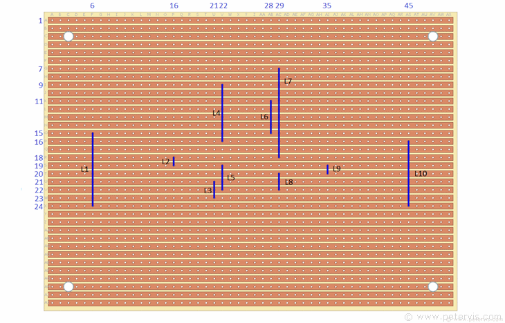
Cut Locations

Link Locations

This Article Continues...
Quadraphonic SQ Decoder -- Part 1Completed Build
Installing Links
Components
Soldering
