Voltmeter Kit Power Supply Circuit
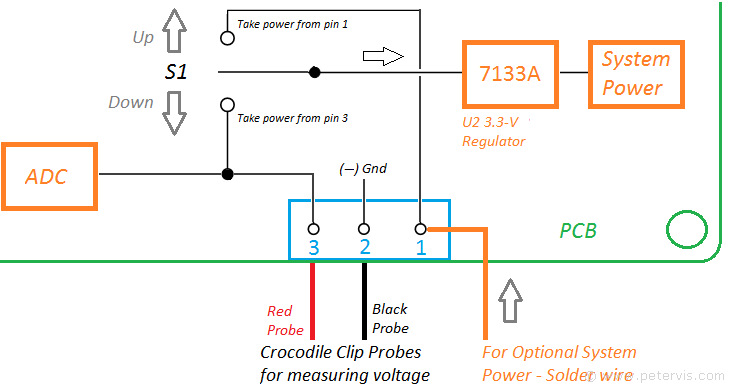
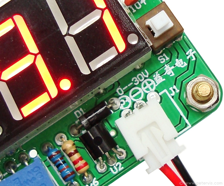
There was no circuit diagram accompanying this voltmeter; however, the board has some Chinese writing that explains how to connect the socket. As it just so happens to be, I do not speak a word of Chinese! I do speak the universal language of electronic engineering, and logically, we can deduce that since the centre pin is negative, as there is a (-) mark next to it, we need the black wire (on the plug end) to connect to that. Therefore, the red wire, in any case, can only connect to the left pin from the centre because the plug connects to the socket in only one way.
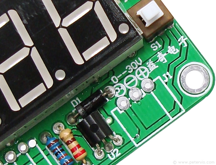
Studying the tracks on the PCB, we can see that the outer two pins connect directly to the selector switch S1. The system can therefore select power (+) from either one or the other pins, but not both simultaneously. Therefore, the unconnected pad right of the centre, is for connecting a dedicated power supply.
The switch S1 therefore selects where the system takes its power. It can take it either from the voltage being measured, i.e. from the red probe (with switch shaft pressed in), or take it from the unconnected pad on the right (with switch shaft up). Therefore, should you decide to build a dedicated power supply for it in the future, then one simply has to feed the positive rail through the unconnected pad on the right, with the switch shaft in the fully up position.
This Article Continues...
Voltmeter KitProbes
Power Supply
Kit of Parts