Zenith Royal 3000-1 Repair and Servicing


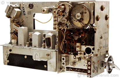
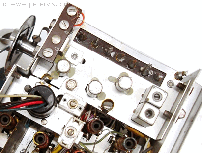
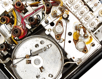
An eBay buyer sent me this Zenith Royal 3000-1 shortwave radio for repair, and occasionally if something takes my interest then, I might take up the offer. This radio has an interesting historical background, and besides I got the chance to photograph it for this article. This is a straightforward textbook heterodyne radio design, but without a printed circuit board, hence you end up chasing wires and components all over the place, which can be annoying. Locating a component shown in the circuit diagram to its actual placement on the tag board can be tricky. However, since the coils are easily locatable, that is a good reference point to start.
The parts are extremely difficult to find, and nobody today will stock germanium transistors, hence you will need to rely on your stash of recycled parts or have friends who might have some transistors that have a chance of working.
This radio has a large number of slug tuned coils and trimmers, and if you are unlucky, then you could find all of them requiring alignment, because this is the first thing layperson will fiddle with when the radio stops working. In this radio design, the earth and chassis are positive, and if you are not used to these sorts of designs then servicing can be difficult. The voltages shown in the service manual are therefore negative. This radio had the typical problem of missing AM bands, and usually in these cases the FM band is working but barely audible with fuzzy sound.
A Case of the Missing AM bands


Since the FM band was working, I knew that the shared IF stage was working fine and the audio amplification stage was operating within normal parameters. Therefore, through a process of elimination, this leaves only three transistors specific for AM reception. These are namely AM RF (121-44), AM Mixer (121351), and AM Oscillator (121-350). It is all elementary my dear Watson! I thought to myself… These three transistors have very similar electronic characteristics, and it occurred to me to swap the three working ones from the IF stages with these to see if I could still hear the FM band. Sure enough, I could hear the FM band, somewhat more clearly, indicating that the transistors may actually be fine. However, with germanium transistors, they can start to conduct slightly in reverse bias, which can affect critical applications such as an oscillator circuit; therefore, I decided to order some equivalents anyway.

If you were not an engineer, then that is about all you could do however, in my case I was just beginning with the diagnostics. I began measuring the voltages at the seven test points as indicated by the service manual. All the voltages seemed fine except the voltage at test point 1, which was low at 0.3 V. I double-checked to make sure the band was set to LW, and it was, and therefore something was definitely afoot here.

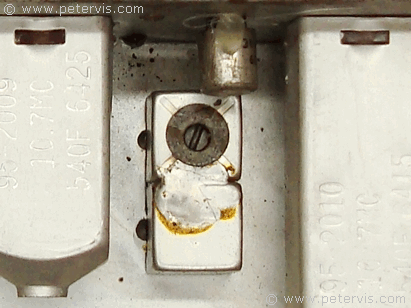
In the circuit diagram, the automatic gain control (AGC) line connects at the base junction of transistor 121-44 (AM RF stage) through a 470 Ω resistor to provide a DC offset. This line goes all the way back to pin 1 of the metal enclosure T11. There is also an 18 kΩ resistor R16 in the middle, so I decided to check it, because these old resistors can increase in value over time causing a voltage drop. My meter measured it to be 22.5 kΩ, so I decided to replace it anyway with a more accurate value. Inside the metal enclosure (T11), there is a diode, which performs the AM detection. Luckily, a pair of capacitors isolates it and therefore pin 4 and pin 3 could be used for testing it. A simple continuity check indicated that it was open. This is one of those times I wished I was wrong because it is inside a metal enclosure, and I would need my high powered soldering iron to remove the solder to gain access. Replacing this diode restored the voltages to their proper operating parameters; and the AM bands came back!
Cleaning Fluids

Avoid getting contact cleaner fluid onto the coils and into those little metal canisters with coils in them. The AM oscillator circuit around transistor 121-350 is extremely sensitive to stray capacitance and inductance, and any cleaning fluids on the coils and components will kill it dead for months until it dries. For each band, the oscillator circuit has to oscillate at a specific frequency, determined by the slug-tuned coils, which provides feedback to the transistor 121-350. Coils L18 to L24 are for that purpose, and selected by the rotary band switch. Do not spray any cleaning fluid on these coils either!
This Article Continues...
Zenith Royal 3000-1Zenith Royal 3000-1 eBay
Zenith Royal 3000-1 Schematic
Zenith Royal 3000-1 AC Adapter
Zenith Royal 3000-1 Repair and Servicing
Zenith Royal 3000-1 121-374 Transistor Mod
Zenith Royal 3000-1 Dial Light Bulb Mod
121-351 Germanium Transistor
121-44 Germanium Transistor
121-350 Germanium Transistor
121-352 Germanium Transistor
Zenith Royal 3000-1 Fuzzy Sound
Zenith Royal 3000-1 Wavemagnet
Zenith Royal 3000-1 Battery Box
Zenith Royal 3000-1 Band Selector Switch
Zenith Royal 3000-1 Chassis Alignment
Zenith Royal 3000-1 Antenna
Zenith Royal 3000-1 Back Cover Lock
