Gertboard Buffered I/O: SN74AC244
I am sure somebody might ask one day what a buffer is and why they should use it on the Gertboard.
A buffer is a temporary data storage element, which came into use during the early development of digital computers. Consequently, it led to the invention of the octal buffer chip, which held a byte of data temporarily. Usually these integrated circuits have an electronic latch mechanism, which prevents the deletion of the stored data. The main application for it was in high-speed bus design within a computer system. The tri-state octal buffers also provided a means to share a bus.
A buffer also has other advantageous qualities such as electrically reshaping the digital signal so that it is a proper square wave. It will also change the signal so that it conforms to correct electrical levels. Therefore, engineers usually use buffers for port circuits where data signals may be travelling between computer systems.
It is without a doubt that high voltages accidentally entering the GPIO pins will damage the Raspberry Pi. If the I / O was through the buffer IC, then it affords protection to the GPIO pins of the Raspberry Pi in case of mistakes in the project circuit. This is why the SN74AC244 octal buffer IC has a chip socket to facilitate easy replacement in case of damage to it.
Design Overview

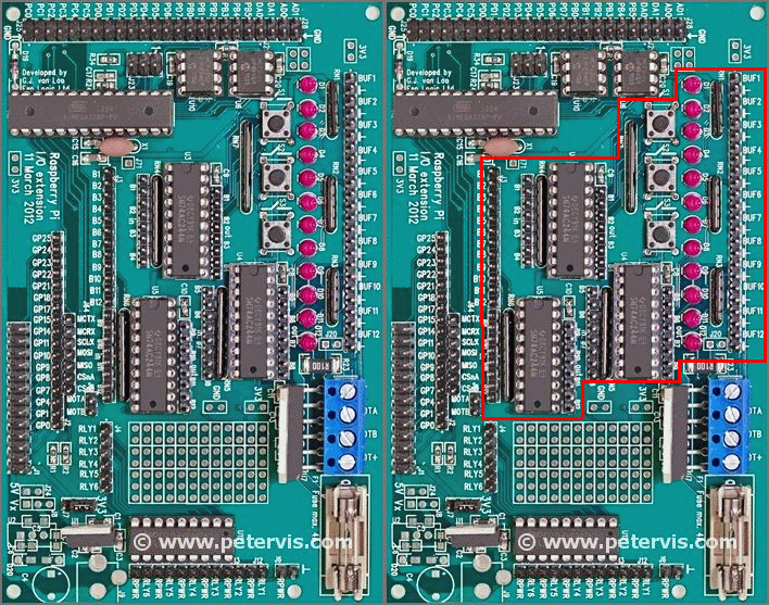
This board provides 12 I/O lines, which are bi-directional, and jumper pins are used to set the direction of the data flow. The design uses three octal buffer chips, which provides 24 buffers; hence, two buffers in either direction per data line are available. The octal buffer chip used is the SN74AC244.
The 12 I/O lines are marked B1 through to B12, and the three switches fixed to B1, B2, B3 lines only.
This board also has 12 LEDs, connected to the 12 I/O lines, which will light in either input mode or output mode. This is very useful because the LED lights on all the lines regardless of the direction of data flow.
Jumper Overview

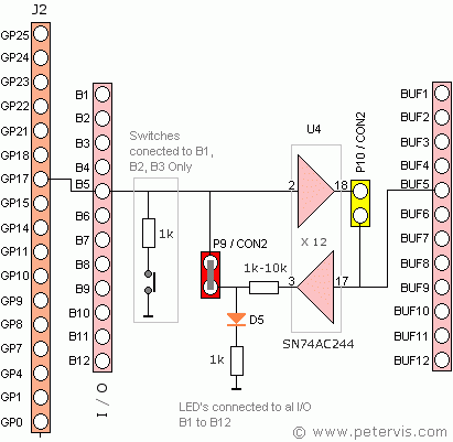
In this example, I have chosen the B5 I/O line to show which jumpers and pins are involved.
On either side of chip U4 there are jumper pins marked B5 to configure the B5 line for either input mode or output mode. The diagram below shows this arrangement in more detail.
Input Mode Setting


When you want a signal from the outside going into the Raspberry Pi, use the P9 / CON2 jumper marked in red as shown below.
Signal Direction: A Signal from BUF5 pin travels to GP17 pin.
Does LED D5 Light-up in this direction? Yes

This shows P9 / CON2 jumper, which must be set when you want a signal from outside project circuits entering into the Raspberry Pi.
Output Mode Setting


When you want a signal from the Raspberry Pi to go to outside projects, use the P10 / CON2 jumper marked in red as shown below.
Signal Direction: A signal from GP17 pin travels to BUF5 pin.
Does LED D5 Light-up in this direction? Yes

This shows P10 / CON2 jumper, which must be set when you want a signal from the Raspberry Pi, going outside to project circuits.
Footnote
On the Gertboard user manual circuit diagram, the P10 / CON2 jumper for the B5 line is incorrect. However, I have drawn it correctly here.
This Article Continues...
Gertboard Raspberry Pi ExpansionGertboard Buffered I/O: SN74AC244
Gertboard Open Collector Drivers: ULN2803APG
Gertboard Motor Controller: L6203
Gertboard ATMega Chip: ATMega168A/PA, and ATMega328/P
Gertboard ADC - Analog to Digital Converter: MCP3002
Gertboard DAC - Digital to Analog Converter: MCP4802
Gertboard GPIO Pins