Raspberry Pi Power Circuit Build


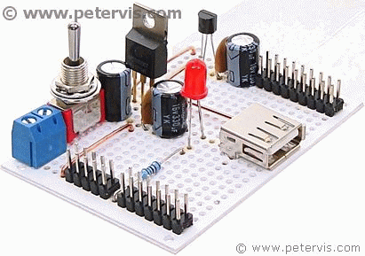
Here is a completed circuit for the Raspberry Pi power supply. It appears and works far better than I had hoped. Those header pins for the ground and 3.3 V power turned out to be very useful after all. If I were to re-design it, I would probably add more USB sockets and connect the data pins into a hub configuration.
FH01B Switch for the PSU

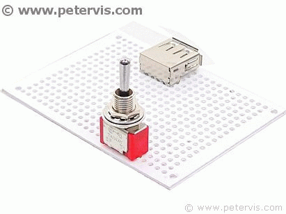
The FH01B is an ON-OFF-ON locking switch, with the centre position as OFF. The contacts are rated at 5 A and 30 V which is perfect for this application.
Drilling Holes

Unfortunately, I still had to drill holes for the switch terminals, however, if you can find cheaper switches with thinner leads then use those.
Circuit with Switch


It fits nicely and looks better than I had hoped. If it was a little cheaper for students and the terminals thin enough to mount onto a PCB, then it would be perfect. If you do not like the idea of drilling onto a PCB, then the switch could mount onto a panel instead. You will just have to solder some jumper leads instead. There are also some cheap latching switches on eBay and Amazon. I managed to find some that were mounted on a PCB and sold in bags of 10 for a few pounds.
Screw Terminal

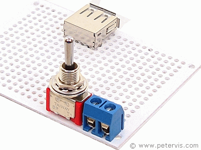
The blue screw terminal fits next to the switch. I managed to get these in a bag of 20 for around a pound. The great thing is that you can use them on many hobby projects.
In the background is the USB socket, which fits perfectly. For more information on how to fit it, please refer to the USB Socket Pinout article. The cable for connecting the USB socket to the Raspberry Pi came from a pound store.
This Article Continues...
Raspberry Pi Power Supply CircuitRaspberry Pi 3.3 V Power Supply
5 V Power Supply Kit with 3.3 V
Raspberry Pi Power Supply Switch
Raspberry Pi Power Circuit Build
Raspberry Pi Power Circuit Results
Reference
5 V Voltage Regulator3.3 V Voltage Regulators
IRFZ44N
