5 V Power Supply Kit with 3.3 V

This Raspberry Pi power supply build uses surface-mount device (SMD) voltage regulators. It makes a great kit for hobbyists and students who are able to work with SMD. This is also a great introductory style project for those new to this technology as it consists of just two SMD voltage regulators in a large SOT-223 package that are easy to handle and solder.
This circuit build uses the AMS1117 series voltage regulator, which is available very cheaply at the rate of ten regulators for around a pound on eBay. This is one of my favourite voltage regulators because it is the easiest SMD to work with. If you are new to using SMD then this might very well be the first component that you solder.
AMS1117 Voltage Regulator
Advanced Monolithic Systems manufactures the AMS1117 voltage regulator IC. It is one of the lowest-cost components used in schools and commercial applications. If you are buying for a school, you can get a quantity of 50 regulators for less than a fiver including postage! This is a high-efficiency regulator that can operate down to 1 V. It has a maximum output current of one ampere. It is available in fixed voltage, and variable voltage versions. For this project, I am using fixed voltage regulators, where Q2 is AMS1117-5.0 to establish the 5 V rail, and Q1 is AMS1117-3.3 to establish the 3.3 V rail.
These regulators are very hardy to short circuits as they have internal circuitry to protect them against overload conditions including thermal overload. Hence, a fuse is not usually required on the output rails. They require a 22 µF capacitor at the output to provide stability. Obviously if you have the budget or some recycled capacitors then you can add more capacitance. Please consult the AMS1117 documentation for more information. The rest of the components used in this circuit are identical to that shown in previous circuits, so just have a look at that.
SOT-223 Soldering Guide
To see how these regulators in a SOT-223 package are installed have a look at my Soldering SMD Guide.
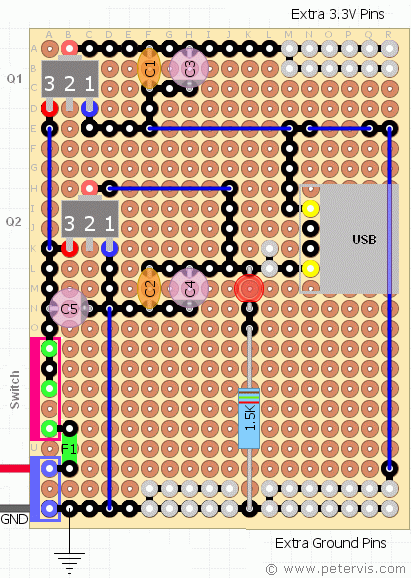
Since this is an SMD, it requires soldering on the copper pad side of the board. The terminals align nicely on the pads and it is a simple job of soldering them. Obviously, if you were to look at it from the component side then the pins would be reversed to 3, 2, and 1.
Luckily, the tab on these voltage regulators is common with the centre pin, voltage out (Vout); hence, by using the tab it is possible to simplify the design by avoiding the use of jumper wires. I do not like to use jumper wires because they look messy.
There is one link routed under the USB socket, which is a thin piece of solid copper wire. Since the socket shield is earth as well, the socket mounts above it without any problems. If you wanted to make the build even easier you could probably do away with C1, C2, and C5, and probably the diode and resistor as well if you do not need them.
Input Power Supply Range
The AMS1117 can accept a maximum input voltage of 15 V DC, and supply a maximum of 1 A output. It can operate right down to 1 V, which is the input-output differential. A conventional transformer based adapter that provides 12 V and 1 A should work fine with this circuit.
This Article Continues...
Raspberry Pi Power Supply CircuitRaspberry Pi 3.3 V Power Supply
5 V Power Supply Kit with 3.3 V
Raspberry Pi Power Supply Switch
Raspberry Pi Power Circuit Build
Raspberry Pi Power Circuit Results
Reference
5 V Voltage Regulator3.3 V Voltage Regulators
IRFZ44N
