Sony TA-VE170 Chipset
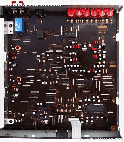
It is a nice PCB layout and design, and the links appear more prominent because of the black colour of the board. There is a wide range of chipsets used from different manufacturers. It has the commonly used LC78212 input selector chip, which is used on many Sony amplifiers. There is also the LV1035M, which is the Dolby Pro Logic decoder chip.
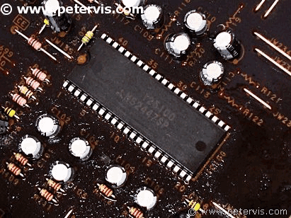
This is the M62447SP sound processor chip. This chip provides an electronic volume control for six channels. It also interfaces with the main system microcontroller chip.
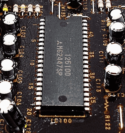
It is an interesting chip in a large PDIP package. I have never seen this one before.
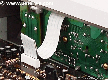
The front panel PCB connects to the audio board via this ribbon cable.
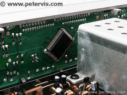
The main system controller is the uPD7804. Pin 16 is for the Protect signal, which is active low. Under normal operations it should read 4.8 V at all times, and goes low to flag the protect mode.
This Article Continues...
Sony TA-VE170 Surround Sound AmplifierSony TA-VE170 Inside
Sony TA-VE170 Back Sockets
Sony TA-VE170 Active Heatsink
Sony TA-VE170 Protect Mode and Fan
Sony TA-VE170 Cooling Fan
Sony TA-VE170 PSU and Standby
Sony TA-VE170 Chipset
