EF50 One Valve Radio Circuit

This EF50 one valve radio circuit operates at very low voltages of just +9 V for the anode, and 6.0 V for the heater filament. I designed this circuit from scratch, and I do not believe anyone has used this combination of components before to make a low-voltage one-valve radio. The specifications and mathematics of the EF50 indicated that it had a good chance of working at low voltages; in practice, it was more straightforward than I hoped. After much experimentation, trying different configurations of grid biasing, I managed to discover one circuit that seems to work extremely well. When I think about it, it was really due to following the best engineering principles and mathematics already known! When you follow those and add a little imagination, almost everything is possible.

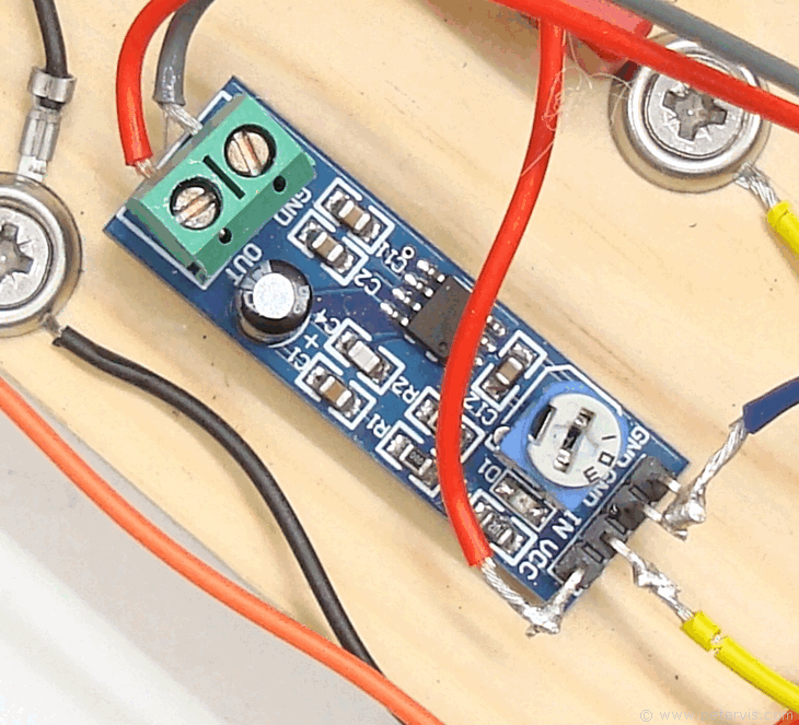
The main reason why this radio works so well is due to the ready-made SMD LM386 amplifier module, which has an internal gain of 200. It cost a princely sum of just one pound and does all the voltage amplification, and current amplification to drive a loudspeaker. I have a number of radio stations located within ten miles and the reception is ear splitting loud with just a small 1 m telescopic antenna. Extending it to 2 m using a wire connected to the ceiling makes it even more loudly. When using a homemade LM386 amplifier, the performance was not as good due to crosstalk caused by the long wires on the breadboard.

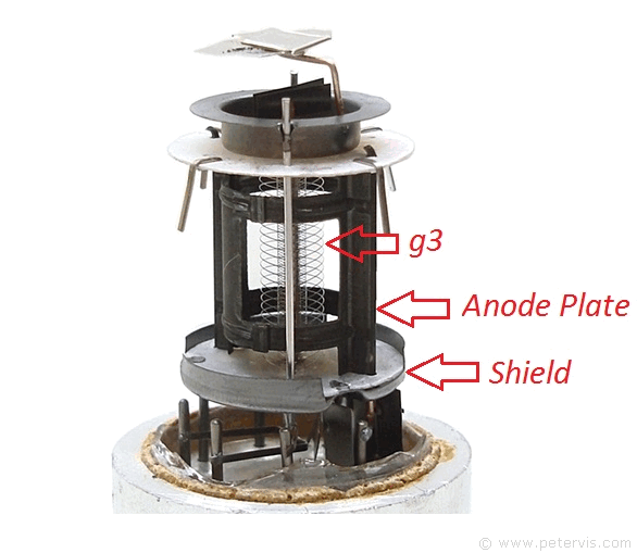
When I first started experimenting, I connected grid 3 to the anode, which is very unconventional, however; my thoughts were that this might be what is required for operating the valve on such low voltages. By connecting the grid in this manner, we can effectively increase the surface area of the anode, and therefore increase the pulling power to attract the electrons even with such a low anode voltage. This worked very well, however I decided to see what would happen if I followed the conventional configuration for pentodes and connect grid 3 (suppressor) to the cathode. Theoretically, this should improve the sensitivity of the input control grid, and it worked!
The 100 pF capacitor from the cathode to anode makes a big difference in the sound and the gain. It removes RF from the anode and placing it there causes a slight gain in the sound. I therefore decided to leave it there. It is customary that when we are not using any reaction techniques, we want as little RF as possible on the anode; hence, we usually make this capacitor as large as possible, whilst simultaneously keeping the reactance favourable for audio frequencies to pass.
Whilst experimenting, I noticed that the addition of a 2 kΩ resistor at the anode was helping to increase the gain. This is because this resistor with the 0.47 µF capacitor forms a simple filter to block RF from going further down the stage. A larger resistor provides better filtering action, however it is at the cost of output level; hence, I have kept the value low.

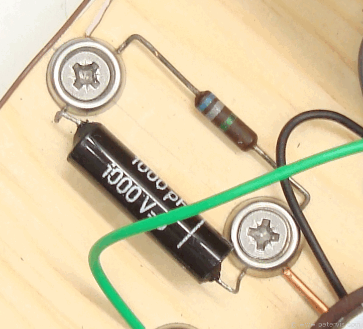
The input to the control grid is through the large value resistor and capacitor in parallel, which provide grid leak. The goal here is to make the capacitor large enough to allow the RF to reach the grid with little or no loss, whilst the resistor is large enough to reduce the damping on the tank circuit. I discovered these values whilst experimenting and find that these high values usually work well in most one-valve radio circuits; hence, this is what I usually start out with.
This Article Continues...
One Valve Radio – EF50 The War HeroEF50
EF50 Pinout
EF50 One Valve Radio Circuit
EF50 One Valve Radio Construction
B9G Paxolin Valve Socket
Installing BG9 Socket
Ferrite Coil and Variable Capacitor
Power Supply Using AC Transformer
Power Supply Using DC Adapter
