Casio Serial Cable Circuit Build
To build the Casio serial cable, you will need some basic components, and this page shows a small part of the circuit build. I was able to use recycled components, as I do not have "Daddy" Warbucks to buy me things.
Recycled Electrolytic Capacitor
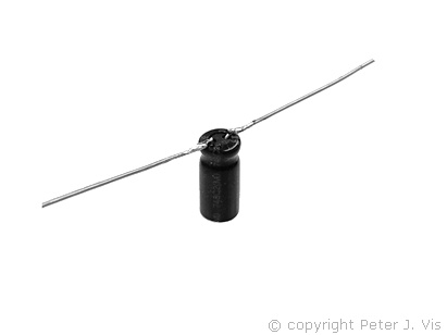
I am using recycled capacitors for this build, and all I had to do was to extend the leads a little, which is no problem.
Soldering Chip Socket
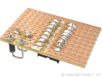
The first step was to install the chip socket and the Schottky diodes. As you can see, I like my soldering to be very shiny. I am using some Omega lead and rosin free solder and my vintage Antex soldering iron for the soldering.
Soldering DB9 Pins
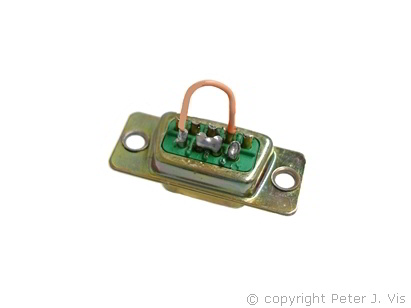
When soldering the DB9, pin 7 and pin 8 are close to each other and joined with a "blob" of solder, whilst pin 4 and pin 6 require a small loop of wire.
The soldering has to be very neat with minimum solder used, as there will be other wires soldered as well. Pin 6 and pin 1 are on the outer left-hand edge; hence, they solder together with a "blob" of solder too. Hence, to recap, pins (1, 4, and 6) join together, and pins (7, 8) join together.
Wiring the Jack Plug
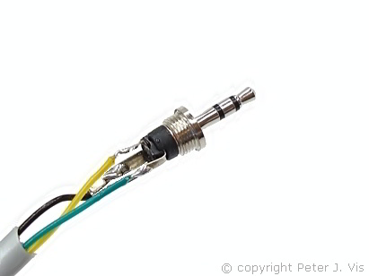
To connect to the jack plug you could use some spare CAT5 cable. There are four pairs in that and you could double a pair and use them together.
DB9 Case
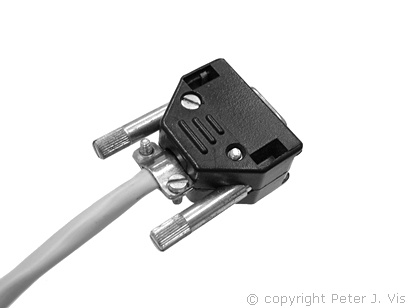
I am using a recycled DB9 socket with case, as they are very expensive therefore; it is a good idea to recycle them when possible. These ones with screw-on cases are very useful and can save a lot of money.
This Article Continues...
Casio Serial CableCasio Cable Circuit
Circuit Power & Serial Port Logic
Casio Cable Circuit Layout
MAX232 Basics for Students
Casio Serial Cable Components
2.5 mm Jack Plug Connection
Casio Serial Cable Circuit Build
Casio Serial Cable Test
Casio Serial Cable Compatibility
Casio Serial Cable Software Configuration