Casio Serial Cable Test
Testing the Casio serial cable circuit is an important stage of the build, because, if there are any errors in the build, then detection and correction is vital. The first part of the checking involves measuring the voltages on the board without the MAX232 chip inserted in the socket.
Checking Voltages
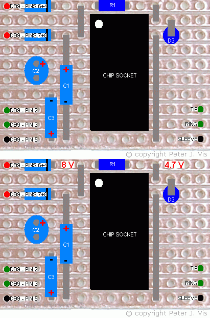
Connect the circuit to the COM1 port (assuming this is the port you are using) of the PC and start the Casio software. When the software starts, pin 4 on the DB9 socket and on the serial port goes HIGH, and there will be approximately 10 V entering D1.
Check the voltages at the points indicated in the diagram above. Before R1 you should read approximately 8 V or more, and after R1 you should have 4.7 V or thereabouts.
Pin 16 (Vcc) should be receiving 4.7 V. If your meter shows 3 V or 3.9 V, then chances are your diode is not the correct type. In addition, check the value of R1 to make sure it is correct. It may also be a good idea to use a continuity meter to check all the adjacent tracks for shorts caused by solder splashes.
Close all programs and Start HyperTerminal. When this program is started, there should be +10 V entering D1, and +10 V entering D2.
Configuring Communication Properties
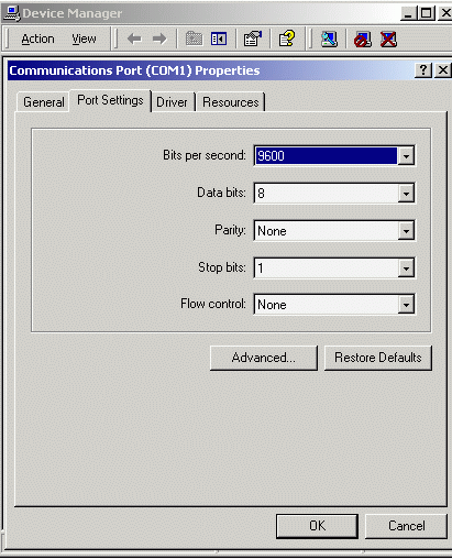
In "Control Panel", "Device Manager", "COM1 Properties", set the values as shown above. Make sure that your calculator can communicate with these values, in particular "9600 bps" and "Parity: None". Bookmark this page and then reboot the PC.
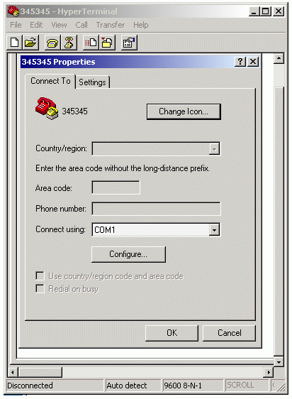
In HyperTerminal, navigate to "File", "Properties", select "COM1" as shown above and press "Configure".
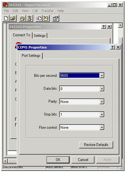
In the "COM1 Properties" window set the parameters as shown above.
Loopback Test
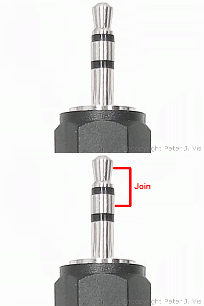
Using a small piece of wire, join the two contacts as shown above, thereby joining the Tx and Rx pins making a loop. In this configuration, whatever the circuit receives loops back to HyperTerminal.
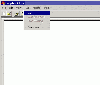
In the "Call" menu, select "Call". When the connection is established, anything you type on the keyboard loops back from the circuit and sent to HyperTerminal for display.
Each character you type on the keyboard travels through the PC serial port, to the MAX232 chip, and to the jack plug where you have looped it with a piece of wire. This data therefore enters back into the MAX232 chip and back to the PC displayed in HyperTerminal.
Changing Parameters
If the characters appear gibberish then use a slower speed by setting the COM 1 port as shown above. If you do not see anything you typed then you need to focus on your circuit and PC configuration. However, if it works then the first thing you should do is press the donate link on my site and donate to the Holocaust Memorial. The next step is to configure the Casio software on the PC so that you may be able to use it for communication with the calculator.
This Article Continues...
Casio Serial CableCasio Cable Circuit
Circuit Power & Serial Port Logic
Casio Cable Circuit Layout
MAX232 Basics for Students
Casio Serial Cable Components
2.5 mm Jack Plug Connection
Casio Serial Cable Circuit Build
Casio Serial Cable Test
Casio Serial Cable Compatibility
Casio Serial Cable Software Configuration