Circuit Power & Serial Port Logic

Understanding how the Casio software such as FA-121, FA-122, FA-123, FA-124, communicates over a serial port in transmit / receive mode required a little research with an oscilloscope. When the software is in transmit / receive mode Pin 4 is the only one that goes high to +10.64 V (on my PC), hence I decided to use this as a source to power the rest of the circuitry. Diode D1 is simply there to block any negative voltages as RS232 voltage levels usually swing between positive and negative.
Using HyperTerminal
HyperTerminal is a very useful program for serial communications debugging and I know that when HyperTerminal is active, pin 4 and pin 7 are both high with +11.17 V, providing the "Flow Control" parameter is "None" in the "COM1 Port Settings" in "Control Panel". Hence, pin 7 is also another source of power that we can use.
With two seperate voltage sources, the circuit should have more than enough power to work. I also have a hunch that other software may make pin 7 high, hence I decided to place a diode D2 and use that pin as a power source as well. I am quite sure that the Casio Diary Software as well as the Texas Instruments software will make that pin high; however, I have not tested that hypothesis since I am only interested in interfacing one Casio calculator for the time being.
Using Schottky Diodes
The diodes used in this circuit are Schottky type; hence, they will have an almost negligible voltage drop across them. You could use the general purpose 1N4148 however, they may cause a significant voltage drop, which may or may not affect the operation of the MAX232. It is difficult to be certain as it depends hugely on the quality of the PC port, and currently there are many variations in industry.
Serial Port Communication
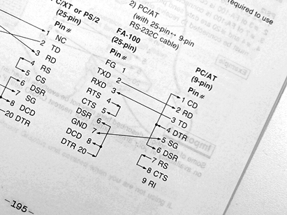
A nice circuit diagram on page 195 of the Casio fx-7700 manual shows how to connect the calculator to a PC serial port for handshake purposes. It shows that pin 4 (DTR) connects to pin 6 (DSR) and pin 1 (CD). It also indicates that pin 7 (RS) and pin 8 (CTS) should be joined, which appears textbook style, hence, I did it that way.
As a Visual Basic programmer, I know that the serial port function usually sits in a loop sensing pin 1 (Carrier Detect) for a signal, before breaking out of the loop. This is why most applications that use the serial port follow the same convention. This is also why one device has to remain in receiving mode sensing for a signal, until the other transmits. I am quite sure that this connecting arrangement will work for a wide range of products from different manufacturers. However as Scotty may say, "I cannot guarantee it though!"
This Article Continues...
Casio Serial CableCasio Cable Circuit
Circuit Power & Serial Port Logic
Casio Cable Circuit Layout
MAX232 Basics for Students
Casio Serial Cable Components
2.5 mm Jack Plug Connection
Casio Serial Cable Circuit Build
Casio Serial Cable Test
Casio Serial Cable Compatibility
Casio Serial Cable Software Configuration