T-100F IF Block


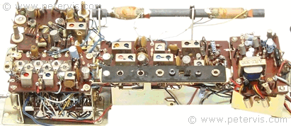
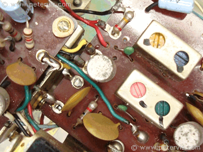
The National Panasonic T-100F radio has the intermediate frequency (IF) block on a separate circuit board. Both FM and AM circuitry share this block. On this chassis, it is the long one near the centre.


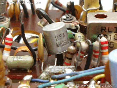
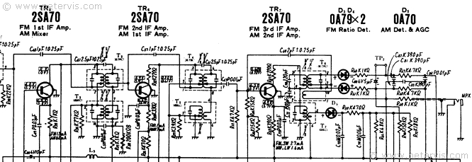
They use 2SA70 transistors in the first, second, and third stages of the IF block, and a pair of OA79 diodes in the third IF stage provides the FM ratio detection. They also tap out the multiplex signal from this stage and make it available through a jack socket marked MPX. This signal has three components consisting of a mixed L+R channel, which is what you hear through this radio. Then there is the L-R signal, which modulates the 38 kHz sub-carrier in a double-sideband suppressed-carrier format. Finally, if memory serves, there is usually a pilot tone as well. The multiplex signal could feed a separate decoder to produce stereo and quadraphonic channels, which I have never seen commercially. At this stage, there are enough signals to produce stereo channels by adding and subtracting them as follows.
(L+R) – (L-R) = 2R
(L+R) + (L-R) = 2L
This is a simple article so I will not delve too deep into it, but it is worth learning the basic principles of radio transmission, because it is very interesting. I used to spend days at the library reading about the importance of a supressed carrier, and transmission energy.


This Article Continues...
National Panasonic T-100FT-100F eBay Cost
T-100F Repair
T-100F Audio Circuit Design
T-100F IF Block
T-100F FM RF Amp
T-100F Chassis
T-100F Batteries
