G. I. Joe Walkie Talkie Field System Inside View
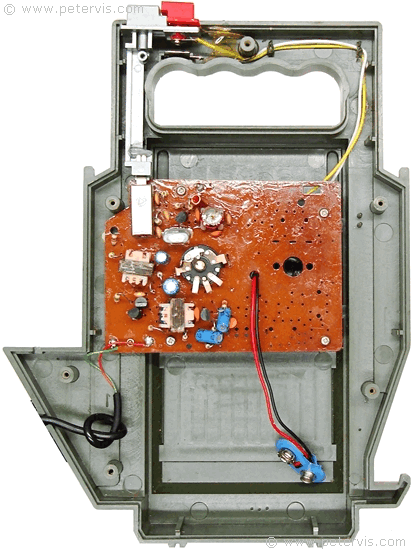


The G. I. Joe Walkie Talkie Field System consists of a printed circuit board with four-transistor circuit. The Push-to-Talk (PTT) switch reconfigures the circuit between being either a transmitter or receiver. Depressing the PTT switch configures the circuit to become a transmitter. During this time, the loudspeaker in the handset behaves as a microphone, and two transistors form the amplifier circuit, whilst the remaining two form the transmitter block. When the PTT switch is not depressed, the circuit becomes a receiver, and two transistors form an amplifier circuit to drive the loudspeaker, whilst the remaining two transistors form the radio receiver.
Radio Circuit
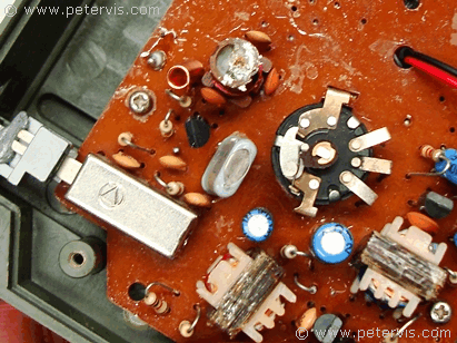
Push-to-Talk (PTT) Circuit Configuration Switch
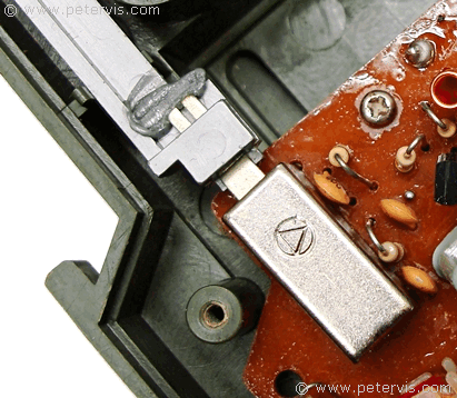
PTT and Signal Buttons
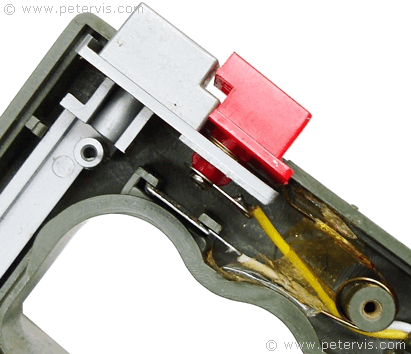
The "Signal" button is the red one, which is for transmitting in Morse code. The grey one is the PTT button. When pressing the red button, the grey one is also depressed due to the interlocking design. There is also a spring, which pushes the red button back up, and usually it detaches from the red button. If yours is also detached, then this photograph shows how it fits.
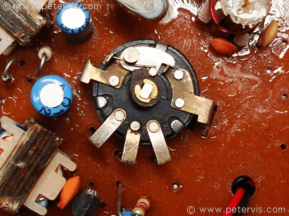
Volume Control and Power Switch
This Article Continues...
G. I. Joe Mobile Field Unit1984 G. I. Joe Mobile Field Unit
G. I. Joe Walkie Talkie Field System Inside View
G. I. Joe Walkie Talkie Handset Inside View
G. I. Joe Walkie Talkie Speaker / Mic Handset
G. I. Joe Walkie Talkie Set Power Supply
G. I. Joe Mobile Field Unit Handset
Walkie Talkie G. I. Joe Repair
