Nokia 3310 Firmware Flashing Cable & Circuit

The Nokia firmware flashing circuit is very simple to build. It mounts on a prototyping board, and amazingly, a very small board is required. Circuits can be built any number of ways on a board and this is one particular way I decided to build it, based on what I had available at the time. Both the MBus and the FBus circuits are on the same board, sharing the single connecting ribbon to the phone port. A simple jumper configuration is used to select between the two buses.
The Build

The surface mount socket looks a bit ghetto. Nevertheless, it really works well. I love the way the ribbon cable socket, and the jumper pins look. I always route wires from above the IC to keep the holes free for connections.
Component Layout


When soldering the DB9 and DB25 sockets, the side shown is the soldering side because that is the side, you will be looking at when soldering the wires to it. I am just a very thoughtful person by nature I suppose. Both circuits are on one board, hence only one connector to the mobile phone is required. Since jumper J1 switches between the buses, both serial and parallel connectors remain connected to the computer simultaneously.
When using the Nokia flashing program, some of its functions require an Mbus connection and therefore J1 should be in the top position as shown. When the program performs firmware read and write functions, the J1 position should be to the lower position. This design is very useful for software development work, and if you are continuously writing code and testing it on the phone, then it is much easier to move J1 than to swap cables around. I managed to learn a lot regarding ARM assembly language programming, and had great fun for a few days.
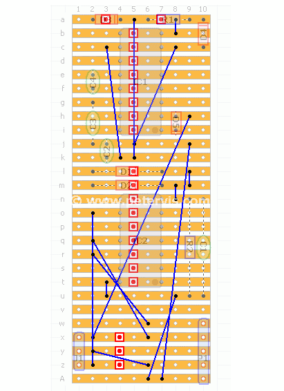
Cutting Tracks and Linking

This image shows where to cut the tracks and where to make the links. If you decide to solder the wires directly to the phone then the special ribbon cable socket is not required.
Ribbon Cable Socket

I used a surface-mount ribbon cable socket, as shown in the Nokia Port Mod article. I did this mod back in 2004 when it was expensive and difficult to obtain the special Nokia 3310 connector. The flexi ribbon cable and surface mount socket came out of an old CD-ROM drive. The socket had very short terminals so I had to extend them with single core wire. It looks a bit ghetto but smart at the same time because of neat soldering. The plastic ribbon cable goes face down, so the exposed copper contacts are facing down. I had to map the bus connections on the ribbon cable first, and then translate it to the board layout.
This Article Continues...
Nokia 3310 Spy Phone ModBMC-3 Battery
M Bus Serial Cable Circuit
Nokia 3310 Parallel Flashing Cable
Nokia 3310 Firmware Flashing Cable & Circuit
Nokia 3310 Port Mod & Firmware Flashing
Testing MBus for Nokia 3310
DCT3 Flasher by Rolis to Back up the Firmware
Nokia 3310 Firmware Updating
Flashing the Nokia 3310
Nokia 3310 Flashing FAQ
Voice Stress Analyser - Lie Detector
Nokia 3310 Network Monitor